 |
Datenblatt-Suchmaschine für elektronische Bauteile |
|
|
Datenblatt-Suchmaschine für elektronische Bauteile |
|
The question interval is too short.
Please try again in a few seconds.

Hello, Please ask a question about USB251 Datasheet
# Example questions:
➢ What does this buffer type signify, and what does 'iclkx' and 'oclkx' signify?
➢ What is the function of the 'vbus_det' pin, and what is the recommended voltage divider configuration for connecting it to the upstream vbus signal?
➢ What are the four possible configurations determined by the 'non_rem[1:0]' pins at reset, and what does each configuration signify regarding port removability?
| Part No. | USB251 |
| Manufacturer | MICROCHIP |
| Size | 810 Kbytes |
| Pages | 57 pages |
| Description | USB 2.0 Hi-Speed Hub Controller |


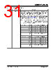






Overall Purpose:
The document excerpt describes the pinout, functionality, and configuration options for a USB 2.0 hub controller chip (the USB251xB/xBi). It details how various pins are used for USB communication, power management, configuration, and other features.
Key Sections & Highlights:
1. Upstream/Downstream USB Interfaces:
- `USBDM_UP`, `USBDP_UP`: Pins for connecting to the host or upstream hub (the device at the very top of the USB chain).
- `VBUS_DET`: Detects if power is being supplied from the upstream host. This is crucial for battery charging and power management.
- `USBDM_DN[x:1]`, `USBDP_DN[x:1]`: Pins for connecting to the USB devices plugged into the hub.
- `PRTPWR[x:1]`, `BC_EN[x:1]`: Power Enable pins for devices downstream.
- `OCS_N[x:1]`: Over-Current Sense input.
2. Serial Port Interfaces:
- `SDA`, `SMBDATA`, `NON_REM1`: Pins for serial communication and system management bus (SMBus).
- `RESET_N`: The reset input signal.
- `SCL`, `SMBCLK`, `CFG_SEL0`: Pins for serial clock and configuration selection.
- `HS_IND`, `CFG_SEL1`: High-speed indicator and configuration selection pin.
3. Miscellaneous Pins:
- `XTALIN`, `CLKIN`, `XTALOUT`: Pins for the crystal oscillator or external clock source.
Important Configuration Details (Key Points):
️· Configuration Selection (CFG_SEL0, CFG_SEL1): These pins are latched during reset and determine the configuration method of the hub (e.g., whether it's a single-speed or high-speed hub, and how it interacts with the host).
️· Port Disable (PRT_DIS_P[x:1], PRT_DIS_M[x:1]): These pins, when pulled high, disable a specific port on the hub.
️· Non-Removable Device Detection (NON_REM1): Indicates whether devices connected to a port are permanently attached.
️· Battery Charging (BC_EN[x:1]): Enables support for USB battery charging protocols.
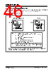
Buffer Types:
The table introduces "Buffer Type" abbreviations:
️· I: Input
️· O: Output
️· OCLKx: Output Clock
️· ICLKx: Input Clock
️· IO: Input/Output
️· I/OSD12: Input/Output - Schmitt Trigger
️· IPU: Input with Pull-Up Resistor
️· I-R: Input with Resistor
Overall Purpose:
The document excerpt describes the pinout, functionality, and configuration options for a USB 2.0 hub controller chip (the USB251xB/xBi). It details how various pins are used for USB communication, power management, configuration, and other features.
Key Sections & Highlights:
1. Upstream/Downstream USB Interfaces:
- `USBDM_UP`, `USBDP_UP`: Pins for connecting to the host or upstream hub (the device at the very top of the USB chain).
- `VBUS_DET`: Detects if power is being supplied from the upstream host. This is crucial for battery charging and power management.
- `USBDM_DN[x:1]`, `USBDP_DN[x:1]`: Pins for connecting to the USB devices plugged into the hub.
- `PRTPWR[x:1]`, `BC_EN[x:1]`: Power Enable pins for devices downstream.
- `OCS_N[x:1]`: Over-Current Sense input.
2. Serial Port Interfaces:
- `SDA`, `SMBDATA`, `NON_REM1`: Pins for serial communication and system management bus (SMBus).
- `RESET_N`: The reset input signal.
- `SCL`, `SMBCLK`, `CFG_SEL0`: Pins for serial clock and configuration selection.
- `HS_IND`, `CFG_SEL1`: High-speed indicator and configuration selection pin.
3. Miscellaneous Pins:
- `XTALIN`, `CLKIN`, `XTALOUT`: Pins for the crystal oscillator or external clock source.
Important Configuration Details (Key Points):
️· Configuration Selection (CFG_SEL0, CFG_SEL1): These pins are latched during reset and determine the configuration method of the hub (e.g., whether it's a single-speed or high-speed hub, and how it interacts with the host).
️· Port Disable (PRT_DIS_P[x:1], PRT_DIS_M[x:1]): These pins, when pulled high, disable a specific port on the hub.
️· Non-Removable Device Detection (NON_REM1): Indicates whether devices connected to a port are permanently attached.
️· Battery Charging (BC_EN[x:1]): Enables support for USB battery charging protocols.
Buffer Types:
The table introduces "Buffer Type" abbreviations:
️· I: Input
️· O: Output
️· OCLKx: Output Clock
️· ICLKx: Input Clock
️· IO: Input/Output
️· I/OSD12: Input/Output - Schmitt Trigger
️· IPU: Input with Pull-Up Resistor
️· I-R: Input with Resistor
| Part No. | USB251 |
| Manufacturer | MICROCHIP |
| Size | 810 Kbytes |
| Pages | 57 pages |
| Description | USB 2.0 Hi-Speed Hub Controller |
| War ALLDATASHEET hilfreich? [ DONATE ] |
Über Alldatasheet | Werbung | Kontakt | Privatsphäre und Datenschutz | Link zum Datenblatt | Linktausch | Hersteller All Rights Reserved©Alldatasheet.com |
| Russian : Alldatasheetru.com | Korean : Alldatasheet.co.kr | Spanish : Alldatasheet.es | French : Alldatasheet.fr | Italian : Alldatasheetit.com Portuguese : Alldatasheetpt.com | Polish : Alldatasheet.pl | Vietnamese : Alldatasheet.vn Indian : Alldatasheet.in | Mexican : Alldatasheet.com.mx | British : Alldatasheet.co.uk | New Zealand : Alldatasheet.co.nz |
|
Family Site : ic2ic.com |
icmetro.com |
 German ▼
  English
 Chinese
 Japanese
 Russian
 Korean
 Spanish
 French
 Italian
 Portuguese
 Polish
 Vietnamese
 Indian
 Mexican
 British
 New Zealand