 |
Datenblatt-Suchmaschine für elektronische Bauteile |
|
|
Datenblatt-Suchmaschine für elektronische Bauteile |
|
The question interval is too short.
Please try again in a few seconds.

Hello, Please ask a question about MP1591DN Datasheet
# Example questions:
➢ What is the recommended crossover frequency for the control loop, and how is it related to the switching frequency?
➢ For a 5v output with a 22µf ceramic capacitor (esr = 10mω), calculate the values of r3 and c4, showing your work.
➢ What are those scenarios and why is the diode beneficial?
| Part No. | MP1591DN |
| Manufacturer | MPS |
| Size | 229 Kbytes |
| Pages | 10 pages |
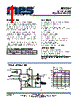
| Description | 2A, 32V, 330KHz Step-Down Converter |


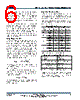
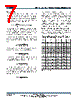
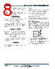

1. Overview & Key Features (implied)
️· The MP1591 is a 2A, 32V, 330kHz step-down converter. This means it can handle a 32V input and deliver up to 2A of current to a lower voltage output.
️· It's a switching regulator, meaning it converts DC voltage efficiently.
️· Careful component selection and compensation are vital for stability and optimal performance.
2. Input Components
️· C1 (Input Capacitor): Not explicitly discussed in detail but assumed to be necessary for filtering input noise and providing a stable voltage source for the converter. The datasheet doesn't offer guidance on this.
️· External Bootstrap Diode (Optional): Recommended for fixed 5V inputs, high duty cycle operation (V<sub>OUT</sub> > 65%), or high input voltages (V<sub>IN</sub> > 12V). A common diode like IN4148 or BAT54 can be used.
3. Output Components
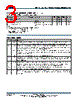
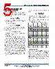
️· C5 (Output Capacitor): Crucial for filtering the output voltage and ensuring stability. The datasheet provides example values in Table 4.
- Types: Ceramic and Special Polymer (SP) capacitors are mentioned. Electrolytic capacitors are also listed for some configurations.
- ESR: The Equivalent Series Resistance of the output capacitor is critical. Higher ESR leads to increased losses and potential instability. The datasheet outlines a check to determine if a second compensation capacitor (C3) is required based on ESR.
️· C2 (Small Ceramic Capacitor): A 10nF ceramic capacitor is typically used close to the MP1591 to improve high-frequency performance.
4. Compensation Components (R3, C3, C4)
️· Purpose: These components are used to stabilize the feedback loop and optimize the regulator's transient response.
️· R3 (Compensation Resistor): Sets the crossover frequency.
- Equation: `R3 ≈ 6.88 x 10^7 * C5 * Vout` (where Vout is in volts and C5 is in Farads, resulting in R3 in ohms)
- Use the *nearest standard value* after calculation.
️· C3 (Second Compensation Capacitor - Optional): Used if the ESR zero of the output capacitor occurs *below* 4x the crossover frequency. It's a way to create additional pole in the feedback loop
- Equation: `C3 = C5 * R_ESR(MAX) / R3`
️· C4 (Compensation Capacitor): Sets a zero in the feedback loop.
- Equation: `C4 > 1.93 x 10^-5 / (π * R3 * fC)` (where fC is the crossover frequency)
5. Stability Considerations & Equations
️· Crossover Frequency (fC): Target approximately 33kHz (1/10th of the switching frequency). Lower frequencies provide slower response, higher frequencies risk instability.
️· ESR Check for C3 Requirement: `8π * C5 * R_ESR(MAX) * fC ≥ 1`
️· Duty Cycle Limit: The datasheet mentions a limit of V<sub>OUT</sub> > 65% to avoid issues. This means the output voltage needs to be at least 65% of the input voltage.
6. Typical Application Circuits
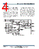
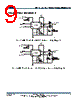
️· Figure 3: Illustrates MP1591 with a Murata 22µF/10V ceramic output capacitor
️· Figure 4: Demonstrates use with a Panasonic 47µF/6.3V Special Polymer output capacitor.
Key Takeaways:
️· Stability is Paramount: Proper compensation is critical for stable operation. Carefully calculate R3, C3 (if needed), and C4 based on the capacitor choices and desired performance.
️· ESR Matters: Consider the ESR of the output capacitor in your calculations.
️· Refer to Table 4: The provided table gives excellent starting points for component values, but always verify through calculation and testing.
️· Test and Verify: After building your circuit, thoroughly test its performance under various load conditions.
1. Overview & Key Features (implied)
️· The MP1591 is a 2A, 32V, 330kHz step-down converter. This means it can handle a 32V input and deliver up to 2A of current to a lower voltage output.
️· It's a switching regulator, meaning it converts DC voltage efficiently.
️· Careful component selection and compensation are vital for stability and optimal performance.
2. Input Components
️· C1 (Input Capacitor): Not explicitly discussed in detail but assumed to be necessary for filtering input noise and providing a stable voltage source for the converter. The datasheet doesn't offer guidance on this.
️· External Bootstrap Diode (Optional): Recommended for fixed 5V inputs, high duty cycle operation (V<sub>OUT</sub> > 65%), or high input voltages (V<sub>IN</sub> > 12V). A common diode like IN4148 or BAT54 can be used.
3. Output Components
️· C5 (Output Capacitor): Crucial for filtering the output voltage and ensuring stability. The datasheet provides example values in Table 4.
- Types: Ceramic and Special Polymer (SP) capacitors are mentioned. Electrolytic capacitors are also listed for some configurations.
- ESR: The Equivalent Series Resistance of the output capacitor is critical. Higher ESR leads to increased losses and potential instability. The datasheet outlines a check to determine if a second compensation capacitor (C3) is required based on ESR.
️· C2 (Small Ceramic Capacitor): A 10nF ceramic capacitor is typically used close to the MP1591 to improve high-frequency performance.
4. Compensation Components (R3, C3, C4)
️· Purpose: These components are used to stabilize the feedback loop and optimize the regulator's transient response.
️· R3 (Compensation Resistor): Sets the crossover frequency.
- Equation: `R3 ≈ 6.88 x 10^7 * C5 * Vout` (where Vout is in volts and C5 is in Farads, resulting in R3 in ohms)
- Use the *nearest standard value* after calculation.
️· C3 (Second Compensation Capacitor - Optional): Used if the ESR zero of the output capacitor occurs *below* 4x the crossover frequency. It's a way to create additional pole in the feedback loop
- Equation: `C3 = C5 * R_ESR(MAX) / R3`
️· C4 (Compensation Capacitor): Sets a zero in the feedback loop.
- Equation: `C4 > 1.93 x 10^-5 / (π * R3 * fC)` (where fC is the crossover frequency)
5. Stability Considerations & Equations
️· Crossover Frequency (fC): Target approximately 33kHz (1/10th of the switching frequency). Lower frequencies provide slower response, higher frequencies risk instability.
️· ESR Check for C3 Requirement: `8π * C5 * R_ESR(MAX) * fC ≥ 1`
️· Duty Cycle Limit: The datasheet mentions a limit of V<sub>OUT</sub> > 65% to avoid issues. This means the output voltage needs to be at least 65% of the input voltage.
6. Typical Application Circuits
️· Figure 3: Illustrates MP1591 with a Murata 22µF/10V ceramic output capacitor
️· Figure 4: Demonstrates use with a Panasonic 47µF/6.3V Special Polymer output capacitor.
Key Takeaways:
️· Stability is Paramount: Proper compensation is critical for stable operation. Carefully calculate R3, C3 (if needed), and C4 based on the capacitor choices and desired performance.
️· ESR Matters: Consider the ESR of the output capacitor in your calculations.
️· Refer to Table 4: The provided table gives excellent starting points for component values, but always verify through calculation and testing.
️· Test and Verify: After building your circuit, thoroughly test its performance under various load conditions.
| Part No. | MP1591DN |
| Manufacturer | MPS |
| Size | 229 Kbytes |
| Pages | 10 pages |
| Description | 2A, 32V, 330KHz Step-Down Converter |
| War ALLDATASHEET hilfreich? [ DONATE ] |
Über Alldatasheet | Werbung | Kontakt | Privatsphäre und Datenschutz | Link zum Datenblatt | Linktausch | Hersteller All Rights Reserved©Alldatasheet.com |
| Russian : Alldatasheetru.com | Korean : Alldatasheet.co.kr | Spanish : Alldatasheet.es | French : Alldatasheet.fr | Italian : Alldatasheetit.com Portuguese : Alldatasheetpt.com | Polish : Alldatasheet.pl | Vietnamese : Alldatasheet.vn Indian : Alldatasheet.in | Mexican : Alldatasheet.com.mx | British : Alldatasheet.co.uk | New Zealand : Alldatasheet.co.nz |
|
Family Site : ic2ic.com |
icmetro.com |
 German ▼
  English
 Chinese
 Japanese
 Russian
 Korean
 Spanish
 French
 Italian
 Portuguese
 Polish
 Vietnamese
 Indian
 Mexican
 British
 New Zealand