 |
Datenblatt-Suchmaschine für elektronische Bauteile |
|
|
Datenblatt-Suchmaschine für elektronische Bauteile |
|
The question interval is too short.
Please try again in a few seconds.

Hello, Please ask a question about SN54LS298 Datasheet
# Example questions:
➢ What are the key differences between the case 751b-03 and case 648-08 packages described in the document?
➢ What is the significance of the 'setup time' (ts) and 'hold time' (th) parameters as defined in the ac characteristics section?
➢ What is the typical input high voltage (vih) for the sn74ls298?
| Part No. | SN54LS298 |
| Manufacturer | MOTOROLA |
| Size | 187 Kbytes |
| Pages | 6 pages |
| Description | QUAD 2-INPUT MULTIPLEXER WITH STORAGE |


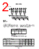


1. Product Overview:
️· Part Number: 54/74LS298
️· Type: 8-Stage Shift Register with 3-State Outputs
️· Function: The 54/74LS298 is a synchronous serial-in, serial-or-parallel-out shift register. It has 8 D-type flip-flops. Data is shifted one stage with each clock pulse. The output can be either serial or parallel.
️· Key Features:
- Synchronous operation
- 3-State outputs (allowing for bus sharing - important for digital systems)
- Versatile: Serial-in, Serial-out or Parallel-out configuration.
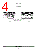
2. Pinout and Package Information:
️· Packages: Available in three different packages:
- Case 620-09 (J): 16-Pin Ceramic DIP (Dual In-Line Package)
- Case 751B-03 (D): 16-Pin Plastic SOIC (Small Outline Integrated Circuit)
- Case 648-08 (N): 16-Pin Plastic SOIC
️· Pin Functions (General): (Refer to the diagrams within the datasheet for exact pin assignments, which depend on the specific package)
- Data Input (D): Serial data input.
- Clock Input (C): Clock signal to shift data.
- Output Enables (OE): Active-low enables. When low, the outputs are enabled; when high, the outputs are in a high-impedance state (disconnected).
- Q0-Q7: The 8 output stages.
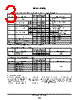
3. Electrical Characteristics (Key Values - Summarized):
These are critical for proper circuit design.
️· Input HIGH Voltage (VIH): 2.0V - 7.0V (depending on if it's 54 or 74 version)
️· Input LOW Voltage (VIL): 0.8V - 0.7V (depending on if it's 54 or 74 version)
️· Output HIGH Voltage (VOH): Typically 3.5V (VCC = 5.0V)
️· Output LOW Voltage (VOL): Typically 0.35V (VCC = 5.0V)
️· Output Enable Voltage (OE): Typically < 0.4 V (for the active low OE signal to be considered active)
️· Power Supply Voltage (VCC): Typically operates between 3.0V to 6.0V, but most often 5.0V.
4. AC Characteristics (Key Parameters - Summarized):
Important for timing in digital circuits.
️· Propagation Delay (CP to Output): Approximately 21-32ns (depends on temperature) – Time it takes for a clock signal to propagate through the register and appear at the output.
️· Clock Pulse Width (tW): Minimum 20ns – The minimum duration of the clock pulse for reliable operation.
️· Data Setup Time (ts): Minimum 15ns – Time data must be stable *before* the clock edge.
️· Data Hold Time (th): Minimum 5ns – Time data must remain stable *after* the clock edge.
5. Operating Modes & Configurations:
️· Serial-In, Serial-Out: Standard shift register operation.
️· Serial-In, Parallel-Out: Connect all Q0-Q7 outputs to a parallel bus. This allows for faster data transfer from the register.
️· 3-State Operation: Use the output enable (OE) pins to control the state of the outputs. Connect multiple devices to a common bus.
6. Important Considerations & Cautions:
️· 3-State Outputs: Understand how these outputs behave when not actively driving a signal. They effectively disconnect from the circuit.
️· Timing: Carefully analyze the setup and hold times to ensure proper circuit operation.
️· Power Supply: Ensure a stable and clean power supply.
️· Motorola Disclaimer: The datasheet contains a standard disclaimer about product suitability, warranty, and liability.
1. Product Overview:
️· Part Number: 54/74LS298
️· Type: 8-Stage Shift Register with 3-State Outputs
️· Function: The 54/74LS298 is a synchronous serial-in, serial-or-parallel-out shift register. It has 8 D-type flip-flops. Data is shifted one stage with each clock pulse. The output can be either serial or parallel.
️· Key Features:
- Synchronous operation
- 3-State outputs (allowing for bus sharing - important for digital systems)
- Versatile: Serial-in, Serial-out or Parallel-out configuration.
2. Pinout and Package Information:
️· Packages: Available in three different packages:
- Case 620-09 (J): 16-Pin Ceramic DIP (Dual In-Line Package)
- Case 751B-03 (D): 16-Pin Plastic SOIC (Small Outline Integrated Circuit)
- Case 648-08 (N): 16-Pin Plastic SOIC
️· Pin Functions (General): (Refer to the diagrams within the datasheet for exact pin assignments, which depend on the specific package)
- Data Input (D): Serial data input.
- Clock Input (C): Clock signal to shift data.
- Output Enables (OE): Active-low enables. When low, the outputs are enabled; when high, the outputs are in a high-impedance state (disconnected).
- Q0-Q7: The 8 output stages.
3. Electrical Characteristics (Key Values - Summarized):
These are critical for proper circuit design.
️· Input HIGH Voltage (VIH): 2.0V - 7.0V (depending on if it's 54 or 74 version)
️· Input LOW Voltage (VIL): 0.8V - 0.7V (depending on if it's 54 or 74 version)
️· Output HIGH Voltage (VOH): Typically 3.5V (VCC = 5.0V)
️· Output LOW Voltage (VOL): Typically 0.35V (VCC = 5.0V)
️· Output Enable Voltage (OE): Typically < 0.4 V (for the active low OE signal to be considered active)
️· Power Supply Voltage (VCC): Typically operates between 3.0V to 6.0V, but most often 5.0V.
4. AC Characteristics (Key Parameters - Summarized):
Important for timing in digital circuits.
️· Propagation Delay (CP to Output): Approximately 21-32ns (depends on temperature) – Time it takes for a clock signal to propagate through the register and appear at the output.
️· Clock Pulse Width (tW): Minimum 20ns – The minimum duration of the clock pulse for reliable operation.
️· Data Setup Time (ts): Minimum 15ns – Time data must be stable *before* the clock edge.
️· Data Hold Time (th): Minimum 5ns – Time data must remain stable *after* the clock edge.
5. Operating Modes & Configurations:
️· Serial-In, Serial-Out: Standard shift register operation.
️· Serial-In, Parallel-Out: Connect all Q0-Q7 outputs to a parallel bus. This allows for faster data transfer from the register.
️· 3-State Operation: Use the output enable (OE) pins to control the state of the outputs. Connect multiple devices to a common bus.
6. Important Considerations & Cautions:
️· 3-State Outputs: Understand how these outputs behave when not actively driving a signal. They effectively disconnect from the circuit.
️· Timing: Carefully analyze the setup and hold times to ensure proper circuit operation.
️· Power Supply: Ensure a stable and clean power supply.
️· Motorola Disclaimer: The datasheet contains a standard disclaimer about product suitability, warranty, and liability.
| Part No. | SN54LS298 |
| Manufacturer | MOTOROLA |
| Size | 187 Kbytes |
| Pages | 6 pages |
| Description | QUAD 2-INPUT MULTIPLEXER WITH STORAGE |
| War ALLDATASHEET hilfreich? [ DONATE ] |
Über Alldatasheet | Werbung | Kontakt | Privatsphäre und Datenschutz | Link zum Datenblatt | Linktausch | Hersteller All Rights Reserved©Alldatasheet.com |
| Russian : Alldatasheetru.com | Korean : Alldatasheet.co.kr | Spanish : Alldatasheet.es | French : Alldatasheet.fr | Italian : Alldatasheetit.com Portuguese : Alldatasheetpt.com | Polish : Alldatasheet.pl | Vietnamese : Alldatasheet.vn Indian : Alldatasheet.in | Mexican : Alldatasheet.com.mx | British : Alldatasheet.co.uk | New Zealand : Alldatasheet.co.nz |
|
Family Site : ic2ic.com |
icmetro.com |
 German ▼
  English
 Chinese
 Japanese
 Russian
 Korean
 Spanish
 French
 Italian
 Portuguese
 Polish
 Vietnamese
 Indian
 Mexican
 British
 New Zealand