 |
Datenblatt-Suchmaschine für elektronische Bauteile |
|
|
Datenblatt-Suchmaschine für elektronische Bauteile |
|
The question interval is too short.
Please try again in a few seconds.

Hello, Please ask a question about RFSA2624SQ Datasheet
# Example questions:
➢ What is the minimum pulse width for the clk signal?
➢ What does 'dnp' signify in this context?
➢ What manufacturer provides the usb to serial uart module (m1)?
| Part No. | RFSA2624SQ |
| Manufacturer | RFMD |
| Size | 920 Kbytes |
| Pages | 9 pages |
| Description | SERIAL CONTROLLED DIGITAL STEP ATTENUATOR 50MHz to 4000MHz, 6-BIT, 0.5dB |

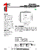
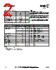


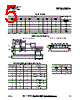
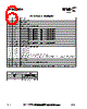

1. Document Type & Purpose:
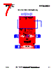
️· This is a datasheet/documentation for an evaluation board (RFSA2714) designed to evaluate the RFSA2624 serial 0.5dB step attenuator IC from RFMD.
️· It provides information for setting up, operating, and understanding the evaluation board.
2. Key Components & Functionality:
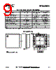
️· RFSA2624: The core component being evaluated – a 6-bit serial attenuator.
️· Evaluation Board: Designed to easily test and interface with the RFSA2624.
️· Serial Interface: The attenuator is controlled via a serial interface (likely SPI or similar). The board incorporates a USB to Serial UART converter.
️· SMA Connectors: RF in/out connections are made through SMA connectors (J1, J2, J99, J100).
3. Board Layout and Connections:
️· Connectors:
- J1-J2 & J99-J100: SMA connectors for RF input and output.
- P1: Header connector for power supply and possible control signals.
- P2: 24-pin DIP connector for serial communication (connected to the UM232R USB to Serial UART module).
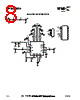
️· Key Components on the Board: Capacitors (C1-C20), resistors (R1-R8), the RFSA2624 attenuator (U1), and the USB-to-Serial converter module (M1).
️· Power Supply: The board requires a DC power supply (voltage not explicitly specified in the text).
4. Bill of Materials (BOM):
️· The document provides a partial BOM, listing key components, manufacturers, and manufacturer part numbers.
️· It specifies the manufacturer for the Evaluation Board itself (Dynamic Details (DDI) Toronto).
5. Important Notes:
️· USB to Serial Module: The UM232R USB-to-Serial UART module (M1) is an integral part of the evaluation setup and is connected to the 24-pin DIP connector (P2).
️· Pin Alignment: There is a specific pin alignment of the USB to Serial Module with connector P2.
6. Timing & Control:
️· The documentation does *not* provide specific timing diagrams or detailed control information for the RFSA2624, only that it is a serial control.
In essence, this document allows a user to properly interface with and evaluate the RFSA2624 serial attenuator chip using the RFSA2714 evaluation board.
1. Document Type & Purpose:
️· This is a datasheet/documentation for an evaluation board (RFSA2714) designed to evaluate the RFSA2624 serial 0.5dB step attenuator IC from RFMD.
️· It provides information for setting up, operating, and understanding the evaluation board.
2. Key Components & Functionality:
️· RFSA2624: The core component being evaluated – a 6-bit serial attenuator.
️· Evaluation Board: Designed to easily test and interface with the RFSA2624.
️· Serial Interface: The attenuator is controlled via a serial interface (likely SPI or similar). The board incorporates a USB to Serial UART converter.
️· SMA Connectors: RF in/out connections are made through SMA connectors (J1, J2, J99, J100).
3. Board Layout and Connections:
️· Connectors:
- J1-J2 & J99-J100: SMA connectors for RF input and output.
- P1: Header connector for power supply and possible control signals.
- P2: 24-pin DIP connector for serial communication (connected to the UM232R USB to Serial UART module).
️· Key Components on the Board: Capacitors (C1-C20), resistors (R1-R8), the RFSA2624 attenuator (U1), and the USB-to-Serial converter module (M1).
️· Power Supply: The board requires a DC power supply (voltage not explicitly specified in the text).
4. Bill of Materials (BOM):
️· The document provides a partial BOM, listing key components, manufacturers, and manufacturer part numbers.
️· It specifies the manufacturer for the Evaluation Board itself (Dynamic Details (DDI) Toronto).
5. Important Notes:
️· USB to Serial Module: The UM232R USB-to-Serial UART module (M1) is an integral part of the evaluation setup and is connected to the 24-pin DIP connector (P2).
️· Pin Alignment: There is a specific pin alignment of the USB to Serial Module with connector P2.
6. Timing & Control:
️· The documentation does *not* provide specific timing diagrams or detailed control information for the RFSA2624, only that it is a serial control.
In essence, this document allows a user to properly interface with and evaluate the RFSA2624 serial attenuator chip using the RFSA2714 evaluation board.
| Part No. | RFSA2624SQ |
| Manufacturer | RFMD |
| Size | 920 Kbytes |
| Pages | 9 pages |
| Description | SERIAL CONTROLLED DIGITAL STEP ATTENUATOR 50MHz to 4000MHz, 6-BIT, 0.5dB |
| War ALLDATASHEET hilfreich? [ DONATE ] |
Über Alldatasheet | Werbung | Kontakt | Privatsphäre und Datenschutz | Link zum Datenblatt | Linktausch | Hersteller All Rights Reserved©Alldatasheet.com |
| Russian : Alldatasheetru.com | Korean : Alldatasheet.co.kr | Spanish : Alldatasheet.es | French : Alldatasheet.fr | Italian : Alldatasheetit.com Portuguese : Alldatasheetpt.com | Polish : Alldatasheet.pl | Vietnamese : Alldatasheet.vn Indian : Alldatasheet.in | Mexican : Alldatasheet.com.mx | British : Alldatasheet.co.uk | New Zealand : Alldatasheet.co.nz |
|
Family Site : ic2ic.com |
icmetro.com |
 German ▼
  English
 Chinese
 Japanese
 Russian
 Korean
 Spanish
 French
 Italian
 Portuguese
 Polish
 Vietnamese
 Indian
 Mexican
 British
 New Zealand