|
Datenblatt-Suchmaschine für elektronische Bauteile |
|
|
Datenblatt-Suchmaschine für elektronische Bauteile |
|
MAX15158Z Datenblatt(PDF) 2 Page - Maxim Integrated Products |
|
|
|||||||||||||||||||||||||||||
MAX15158Z Datenblatt(HTML) 2 Page - Maxim Integrated Products |
|
|
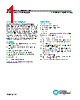
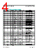
2 / 15 page  Maxim Integrated │ 2 www.maximintegrated.com Evaluates: MAX15158Z MAX15158Z Evaluation Kit Detailed Description of Hardware The MAX15158Z EV kit provides a proven design to evaluate the MAX15158Z, fully integrated, highly efficient, two-phase switching regulator. The EV kit can be easily connected between power input and the load using the banana jacks and connectors provided for the input and output. Test points and connectors are provided to moni- tor and control the device signals. The EV kit operates between input voltage -8V to -60V. The EV kit regulates the output voltage between 3.3V to 60V. The output voltage is set to 35V by default on the EV kit. The output voltage can be changed by changing resistor divider between VOUT+ pin and OUTP pin. Make sure that the correct compensation is selected for stable operation. EN/UVLO Input for the MAX15158Z The device’s enable input (EN/UVLO) is controlled by resistor divider ratio between R19 and R20. The divider ratio is chosen so that the VIN UVLO threshold is set at 21V by default. If EN/UVLO pin voltage is above 1V, MAX15158Z will power up. EN/UVLO pin can be connected to VIN- to disable the regulation. Additionally, a test point (EN) is also provided to drive the EN/UVLO pin. While changing the UVLO threshold, make sure that the UVLO threshold of MAX15158Z is higher than the UVLO threshold of the onboard DRV supply MAX17552 (U4). DRV Supply Selection MAX15158Z and MAX15013 requires a secondary 8V–12V power supply (DRV) for the LDO and gate drive. The supply for DRV pin can be selected from onboard supply by installing shuts across jumpers J3 and J4. Alternatively, an external power supply can be used by applying and 8V–12V between test points VDRV and PGND. Bode Plot 10Ω resistor is installed between VOUT_P sense point and OUTP pin to measure bode plot. BODE+ and BODE- test points are provided on the board on either side of 10Ω resistor for small-signal injection and ability to measure bode plot. Output Regulation VOUT_P and VOUT_N test points are provided to measure the VOUT regulation. Efficiency Measurement VIN_P and VIN_N are provided to measure VIN during efficiency measurement. Also, VOUT_P and VOUT_N are provided to measure VOUT during efficiency measurement. FREQ/CLK Pin Switching frequency is selected by connecting R16 resis- tor between FREQ/CLK pin and VIN-. The switching frequency can also be selected by providing a 480kHz to 4MHz external clock at this pin. A test point (CLOCK) is also provided to drive this pin. REFIN Pin By default, REFIN pin is connected to BIAS supply through R9 (0Ω resistor). R9 can be removed and REFIN can be connected to external supply (between 1V to 2.2V) to change the VOUT reference and therefore change output regulation voltage. The external supply should be applied between test point REFIN and AGND. Connecting Multiple EV Kits Together The EV kit provides jumpers J1, J2, J8, J9, J10, and J11 to connect two EV kits together for four-phase operation. Based on the MAX15158Z data sheet, the EV kits can be configured for master and slave operation. # Denotes RoHS Compliant *Default position Table 1. J3 and J4 Jumper Selection PART TYPE MAX15158ZEVKIT# EV kit JUMPER CONNECTIONS VLDOIN VOLTAGE J3 installed and J4 installed* Onboard Power supply J3 not installed and J4 not installed External Power Supply Ordering Information |
|
|
Link URL |
| War ALLDATASHEET hilfreich? [ DONATE ] |
Über Alldatasheet | Werbung | Kontakt | Privatsphäre und Datenschutz | Link zum Datenblatt | Linktausch | Hersteller All Rights Reserved©Alldatasheet.com |
| Russian : Alldatasheetru.com | Korean : Alldatasheet.co.kr | Spanish : Alldatasheet.es | French : Alldatasheet.fr | Italian : Alldatasheetit.com Portuguese : Alldatasheetpt.com | Polish : Alldatasheet.pl | Vietnamese : Alldatasheet.vn Indian : Alldatasheet.in | Mexican : Alldatasheet.com.mx | British : Alldatasheet.co.uk | New Zealand : Alldatasheet.co.nz |
|
Family Site : ic2ic.com |
icmetro.com |
 German ▼
 English
 Chinese
 German
 Japanese
 Russian
 Korean
 Spanish
 French
 Italian
 Portuguese
 Polish
 Vietnamese
 Indian
 Mexican
 British
 New Zealand