|
Datenblatt-Suchmaschine für elektronische Bauteile |
|
|
Datenblatt-Suchmaschine für elektronische Bauteile |
|
LP3942YQX Datenblatt(PDF) 5 Page - National Semiconductor (TI) |
|
|
|
|||||||||||||||||||||||||||||
LP3942YQX Datenblatt(HTML) 5 Page - National Semiconductor (TI) |
|
|
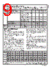
5 / 20 page  Logic Interface Characteristics (1.8V Logic) Symbol Parameter Conditions Limit Units Min Typ Max LOGIC INPUTS V IL Input Low Level SS, SI, SCK, NRST 0.5 V V IH Input High Level SS, SI, SCK, NRST 1.2 V I H Logic Input Current SS, SI, SCK NRST (1 M Ω pull-down) −1 −1 1 3 µA µA f SPI Interface Clock 10 MHz t NRST Reset Pulse Width NRST 50 µs Note 1: Absolute Maximum Ratings indicate limits beyond which damage to the component may occur. Operating Ratings are conditions under which operation of the device is guaranteed. Operating Ratings do not imply guaranteed performance limits. For guaranteed performance limits and associated test conditions, see the Electrical Characteristics tables. Note 2: All voltages are with respect to the potential at the GND pins. Note 3: Internal thermal shutdown circuitry protects the device from permanent damage. Thermal shutdown engages at TJ = 160˚C (typ.) and disengages at TJ = 140˚C (typ.). Note 4: For detailed soldering specifications and information, please refer to National Semiconductor Application Note 1187: Leadless Leadframe Package (LLP). Note 5: The Human body model is a 100 pF capacitor discharged through a 1.5 k Ω resistor into each pin. The machine model is a 200 pF capacitor discharged directly into each pin. MIL-STD-883 3015.7 Note 6: In applications where high power dissipation and/or poor package thermal resistance is present, the maximum ambient temperature may have to be derated. Maximum ambient temperature (TA-MAX) is dependent on the maximum operating junction temperature (TJ-MAX-OP = 105˚C), the maximum power dissipation of the device in the application (PD-MAX), and the junction-to ambient thermal resistance of the part/package in the application (θJA), as given by the following equation: TA-MAX =TJ-MAX-OP −(θJA xPD-MAX). Note 7: Junction-to-ambient thermal resistance ( θJA) is taken from a thermal modeling result, performed under the conditions and guidelines set forth in the JEDEC standard JESD51-7. The test board is a 4-layer FR-4 board measuring 102 mm x 76 mm x 1.6 mm with a 2x1 array of thermal vias. The ground plane on the board is 50 mm x 50 mm. Thickness of copper layers are 36 µm/18 µm/18 µm/36 µm (1.5 oz/1 oz/1 oz/1.5 oz). Ambient temperature in simulation is 22˚C, still air. Power dissipation is 1W. The value of θJA of the LP3942 in LLP-24 could vary widely, depending on PWB material, layout, and environmental conditions. In applications where high maximum power dissipation exists (high VIN, high IOUT), special care must be paid to thermal dissipation issues. For more information on these topics, please refer to Application Note 1187: Leadless Leadframe Package (LLP) and the Power Efficiency and Power Dissipation section of this datasheet. Note 8: Min and Max limits are guaranteed by design, test, or statistical analysis. Typical numbers are not guaranteed, but do represent the most likely norm. Note 9: CIN,COUT, C1, and C2 : Low-ESR Surface-Mount Ceramic Capacitors (MLCCs) used in setting electrical characteristics. Minimum capacitance value for CIN,C1, and C2 capacitors is 70% of nominal value. This tolerance includes manufacturing tolerance, temperature coefficient and voltage dependency (roll-off). COUT minimum effective capacitance value is 3.0 µF. Note 10: Output voltage accuracy does not include VDD (2.78V supply voltage) tolerance. Note 11: The quiescent current does not include the current setting resistors’ current. www.national.com 5 |
|
|
Link URL |
| War ALLDATASHEET hilfreich? [ DONATE ] |
Über Alldatasheet | Werbung | Kontakt | Privatsphäre und Datenschutz | Link zum Datenblatt | Linktausch | Hersteller All Rights Reserved©Alldatasheet.com |
| Russian : Alldatasheetru.com | Korean : Alldatasheet.co.kr | Spanish : Alldatasheet.es | French : Alldatasheet.fr | Italian : Alldatasheetit.com Portuguese : Alldatasheetpt.com | Polish : Alldatasheet.pl | Vietnamese : Alldatasheet.vn Indian : Alldatasheet.in | Mexican : Alldatasheet.com.mx | British : Alldatasheet.co.uk | New Zealand : Alldatasheet.co.nz |
|
Family Site : ic2ic.com |
icmetro.com |
 German ▼
 English
 Chinese
 German
 Japanese
 Russian
 Korean
 Spanish
 French
 Italian
 Portuguese
 Polish
 Vietnamese
 Indian
 Mexican
 British
 New Zealand