|
Datenblatt-Suchmaschine für elektronische Bauteile |
|
|
Datenblatt-Suchmaschine für elektronische Bauteile |
|
400EAFAB1 Datenblatt(PDF) 19 Page - ON Semiconductor |
|
|
|||||||||||||||||||||||||||||
400EAFAB1 Datenblatt(HTML) 19 Page - ON Semiconductor |
|
|
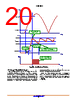
19 / 47 page  NCP12400 www.onsemi.com 19 VCC(min), until the input voltage is high enough to ensure a proper start−up, i.e. when VHV reaches VHV(start). The controller actually starts the next time VCC reaches VCC(on). The controller then delivers pulses, starting with a soft−start period tSSTART during which the peak current linearly increases before the current−mode control takes over. Even though the Dynamic Self−Supply is able to maintain the VCC voltage between VCC(on) and VCC(min) by turning the HV start−up current source on and off, it can only be used in light load condition, otherwise the power dissipation on the die would be too much. As a result, an auxiliary voltage source is needed to supply VCC during normal operation. The Dynamic Self−Supply is useful to keep the controller alive when no switching pulses are delivered, e.g. in brown−out condition, or to prevent the controller from stopping during load transients when the VCC might drop. The NCP12400 accepts a supply voltage as high as 28 V, with an overvoltage threshold VCC(ovp) that latches the controller off. Figure 46. VCC Start−up Timing Diagram time VHV time VCC time DRV VHV(start) V HV(min) VCC(on) V CC(min) HV current source = Istart1 HV current source = Istart2 Waits next VCC(on) before starting VCC(inhibit) For safety reasons, the start−up current is lowered when VCC is below VCC(inhibit), to reduce the power dissipation in case the VCC pin is shorted to GND (in case of VCC capacitor failure, or external pull−down on VCC to disable the controller). There is only one condition for which the current source doesn’t turn on when VCC reaches VCC(inhibit): the voltage on HV pin is too low (below VHV(min)). |
|
Link URL |
| War ALLDATASHEET hilfreich? [ DONATE ] |
Über Alldatasheet | Werbung | Kontakt | Privatsphäre und Datenschutz | Link zum Datenblatt | Linktausch | Hersteller All Rights Reserved©Alldatasheet.com |
| Russian : Alldatasheetru.com | Korean : Alldatasheet.co.kr | Spanish : Alldatasheet.es | French : Alldatasheet.fr | Italian : Alldatasheetit.com Portuguese : Alldatasheetpt.com | Polish : Alldatasheet.pl | Vietnamese : Alldatasheet.vn Indian : Alldatasheet.in | Mexican : Alldatasheet.com.mx | British : Alldatasheet.co.uk | New Zealand : Alldatasheet.co.nz |
|
Family Site : ic2ic.com |
icmetro.com |
 German ▼
 English
 Chinese
 German
 Japanese
 Russian
 Korean
 Spanish
 French
 Italian
 Portuguese
 Polish
 Vietnamese
 Indian
 Mexican
 British
 New Zealand