|
Datenblatt-Suchmaschine für elektronische Bauteile |
|
|
Datenblatt-Suchmaschine für elektronische Bauteile |
|
AD8352ACPZ-R7 Datenblatt(PDF) 13 Page - Analog Devices |
|
|
|||||||||||||||||||||||||||||
AD8352ACPZ-R7 Datenblatt(HTML) 13 Page - Analog Devices |
|
|
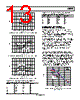
13 / 20 page  AD8352 Rev. A | Page 13 of 20 –60 –110 FREQUENCY (MHz) 10 70 140 190 240 –70 –80 –90 –100 3RDS, 2V p-p OUT 3RDS, 1V p-p OUT Figure 29. Single-Ended, Third-Order Harmonic Distortion, 200 Ω Load –60 –110 FREQUENCY (MHz) 10 70 140 190 240 –70 –80 –90 –100 2NDS, 1V p-p OUT 2NDS, 2V p-p OUT Figure 30. Single-Ended, Second-Order Harmonic Distortion, 1 kΩ Load –60 –110 FREQUENCY (MHz) 10 70 140 190 240 –70 –80 –90 –100 3RDS, 1V p-p OUT 3RDS, 2V p-p OUT Figure 31. Single-Ended, Third-Order Harmonic Distortion, 1 kΩ Load Table 7. Distortion Cancellation Selection Components (RD and CD) for Required Gain, 200 Ω Load AV (dB) RG (Ω) CD (pF) RD (kΩ) 3 4.3 k Open 4.3 6 540 Open 4.3 9 220 0.1 4.3 12 120 0.3 4.3 15 68 0.6 4.3 18 43 0.9 4.3 Table 8. Distortion Cancellation Selection Components (RD and CD) for Required Gain, 1 kΩ Load AV (dB) RG (Ω) CD (pF) RD (kΩ) 6 3 k Open 4.3 9 470 Open 4.3 12 210 0.2 4.3 15 120 0.3 4.3 18 68 0.5 4.3 NARROW-BAND, THIRD-ORDER INTERMODULATION CANCELLATION Broadband, single tone, third-order harmonic optimization does not necessarily result in optimum (minimum) two tone, third-order intermodulation levels. The specified values for CD and RD in Table 5 and Table 6 were determined for minimizing broadband, single tone, third-order levels. Due to phase-related distortion coefficients, optimizing single tone, third-order distortion does not result in optimum in band (2f1 − f2 and 2f2 − f1), third-order distortion levels. By proper selection of CD (using a fixed 4.3 kΩ RD), IP3s of better than 45 dBm are achieved. This results in degraded out-of-band, third-order frequencies (f2 + 2f1, f1 + 2f2, 3f1 and 3f2). Thus, careful frequency planning is required to determine the tradeoffs. Figure 32 shows narrow band (2 MHz spacing) OIP3 levels optimized at 32 MHz, 70 MHz, 100 MHz, and 180 MHz using the CD values specified in Figure 33. These four data points (the CD value and associated IP3 levels) are extrapolated to provide close estimates of IP3 levels for any specific frequency between 30 MHz and 180 MHz. For frequencies below approximately 140 MHz, narrow-band tuning of IP3 results in relatively higher IP3s (vs. the broadband results shown in Table 2 specifications). Though not shown, frequencies below 30 MHz also result in improved IP3s when using proper values for CD. 48 38 02 FREQUENCY (MHz) 00 47 46 45 44 43 42 41 40 39 50 100 150 RL = 200Ω RD = 4.3kΩ CD = 0.3pF 6dB 10dB 15dB 18dB AV = Figure 32. Third-Order Intermodulation Distortion vs. Frequency for Various Gain Settings |
|
|
Link URL |
| War ALLDATASHEET hilfreich? [ DONATE ] |
Über Alldatasheet | Werbung | Kontakt | Privatsphäre und Datenschutz | Link zum Datenblatt | Linktausch | Hersteller All Rights Reserved©Alldatasheet.com |
| Russian : Alldatasheetru.com | Korean : Alldatasheet.co.kr | Spanish : Alldatasheet.es | French : Alldatasheet.fr | Italian : Alldatasheetit.com Portuguese : Alldatasheetpt.com | Polish : Alldatasheet.pl | Vietnamese : Alldatasheet.vn Indian : Alldatasheet.in | Mexican : Alldatasheet.com.mx | British : Alldatasheet.co.uk | New Zealand : Alldatasheet.co.nz |
|
Family Site : ic2ic.com |
icmetro.com |
 German ▼
 English
 Chinese
 German
 Japanese
 Russian
 Korean
 Spanish
 French
 Italian
 Portuguese
 Polish
 Vietnamese
 Indian
 Mexican
 British
 New Zealand