|
Datenblatt-Suchmaschine für elektronische Bauteile |
|
|
Datenblatt-Suchmaschine für elektronische Bauteile |
|
HCS300-/P Datenblatt(PDF) 9 Page - Microchip Technology |
|
|
|||||||||||||||||||||||||||||
HCS300-/P Datenblatt(HTML) 9 Page - Microchip Technology |
|
|
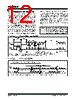
9 / 28 page  © 2001 Microchip Technology Inc. DS21137F-page 9 HCS300 4.3 Synchronous Transmission Mode Synchronous Transmission mode can be used to clock the code word out using an external clock. To enter Synchronous Transmission mode, the Pro- gramming mode start-up sequence must be executed as shown in Figure 4-3. If either S1 or S0 is set on the falling edge of S2 (or S3), the device enters Synchro- nous Transmission mode. In this mode, it functions as a normal transmitter, with the exception that the timing of the PWM data string is controlled externally and 16 extra bits are transmitted at the end with the code word. The button code will be the S0, S1 value at the falling edge of S2 or S3. The timing of the PWM data string is controlled by supplying a clock on S2 or S3 and should not exceed 20 kHz. The code word is the same as in PWM mode with 16 reserved bits at the end of the word. The reserved bits can be ignored. When in Syn- chronous Transmission mode S2 or S3 should not be toggled until all internal processing has been com- pleted as shown in Figure 4-4. FIGURE 4-3: SYNCHRONOUS TRANSMISSION MODE FIGURE 4-4: CODE WORD ORGANIZATION (SYNCHRONOUS TRANSMISSION MODE) “01,10,11” PWM S2 S[1:0] TPS TPH1 TPH2 t = 50ms Preamble Header Data Reserved (16 bits) Padding (2 bits) Button Status S2 S1 S0 S3 Serial Number (28 bits) Button Status S2 S1 S0 S3 DISC+ OVR (12 bits) Sync Counter (16 bits) 82 Data bits Transmitted LSb first. LSb MSb Fixed Portion Encrypted Portion |
|
Link URL |
| War ALLDATASHEET hilfreich? [ DONATE ] |
Über Alldatasheet | Werbung | Kontakt | Privatsphäre und Datenschutz | Link zum Datenblatt | Linktausch | Hersteller All Rights Reserved©Alldatasheet.com |
| Russian : Alldatasheetru.com | Korean : Alldatasheet.co.kr | Spanish : Alldatasheet.es | French : Alldatasheet.fr | Italian : Alldatasheetit.com Portuguese : Alldatasheetpt.com | Polish : Alldatasheet.pl | Vietnamese : Alldatasheet.vn Indian : Alldatasheet.in | Mexican : Alldatasheet.com.mx | British : Alldatasheet.co.uk | New Zealand : Alldatasheet.co.nz |
|
Family Site : ic2ic.com |
icmetro.com |
 German ▼
 English
 Chinese
 German
 Japanese
 Russian
 Korean
 Spanish
 French
 Italian
 Portuguese
 Polish
 Vietnamese
 Indian
 Mexican
 British
 New Zealand