|
Datenblatt-Suchmaschine für elektronische Bauteile |
|
|
Datenblatt-Suchmaschine für elektronische Bauteile |
|
ADL8106ACEZ-R7 Datenblatt(PDF) 24 Page - Analog Devices |
|
|
|||||||||||||||||||||||||||||
ADL8106ACEZ-R7 Datenblatt(HTML) 24 Page - Analog Devices |
|
|
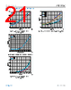
24 / 26 page  Data Sheet ADL8106 APPLICATIONS INFORMATION analog.com Rev. B | 24 of 26 Figure 89. Active Bias Control of the ADL8106 Using the HMC920 HMC920 Bias Sequence When the ADL8106 bias control circuit (HMC920) is set up, the bias can be toggled on and off by applying 3.5 V (high) or 0 V (low) to the EN pin. If EN is left floating, the pin floats high. When EN is set to 3.5 V, the gate voltage (VGATE) initially drops to −2 V and the drain voltage (VDRAIN) rises to +3 V. Then, VGATE and the VGG1 voltage (VGG1) increase until the drain current (IDRAIN) reaches its target value. The closed control loop then regulates IDRAIN to its target value. When the EN pin goes low, VGATE and VGG1 drop back to −2 V, and VDRAIN drops to 0 V. Constant Drain Current Biasing vs. Constant Gate Voltage Biasing In comparison to a constant gate voltage bias, where the current increases dynamically when RF power is applied, constant drain current bias results in constant power consumption. The performance of the constant drain current circuit is summarized in Figure 90 to Figure 95. These figures include comparisons with constant gate voltage bias. The OP1dB and PSAT performance for the constant drain current bias can be varied by varying the drain current setpoint. By increas- ing the bias current, OP1dB and PSAT improve as shown in Figure 92 and Figure 95. The trade-off with constant drain current is that the drain current is present for all RF input and output power levels. Note that Figure 90 indicates a current consumption of 175 mA, which includes the complete current consumption of the circuit, that is, 140 mA drain current for the ADL8106 and an additional 35 mA of IDQ in the HMC920. Also, the PAE for constant drain current bias in Figure 93 assumes a supply voltage of 5 V (the supply voltage to the HMC920) and a constant current of 175 mA. Figure 90. IDD vs. PIN, VDD = 3 V, Frequency = 36 GHz, Constant Drain Current Bias (140 mA + 35 mA) and Constant Gate Voltage Bias (IDQ = 120 mA) Figure 91. OP1dB vs. Frequency for Various Temperatures, Data Measured with Constant Drain Current of 140 mA |
|
|
Link URL |
| War ALLDATASHEET hilfreich? [ DONATE ] |
Über Alldatasheet | Werbung | Kontakt | Privatsphäre und Datenschutz | Link zum Datenblatt | Linktausch | Hersteller All Rights Reserved©Alldatasheet.com |
| Russian : Alldatasheetru.com | Korean : Alldatasheet.co.kr | Spanish : Alldatasheet.es | French : Alldatasheet.fr | Italian : Alldatasheetit.com Portuguese : Alldatasheetpt.com | Polish : Alldatasheet.pl | Vietnamese : Alldatasheet.vn Indian : Alldatasheet.in | Mexican : Alldatasheet.com.mx | British : Alldatasheet.co.uk | New Zealand : Alldatasheet.co.nz |
|
Family Site : ic2ic.com |
icmetro.com |
 German ▼
 English
 Chinese
 German
 Japanese
 Russian
 Korean
 Spanish
 French
 Italian
 Portuguese
 Polish
 Vietnamese
 Indian
 Mexican
 British
 New Zealand