|
Datenblatt-Suchmaschine für elektronische Bauteile |
|
|
Datenblatt-Suchmaschine für elektronische Bauteile |
|
ACT4530M Datenblatt(PDF) 10 Page - Qorvo, Inc |
|
|
|||||||||||||||||||||||||||||
ACT4530M Datenblatt(HTML) 10 Page - Qorvo, Inc |
|
|
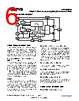
10 / 15 page  Data Sheet Rev. B, September 2019 | Subject to change without notice 10 of 15 www.qorvo.com © 2020 Qorvo US, Inc. All rights reserved. ACT4530M 40 V/3.0 A CV/CC Buck Converter Featuring QC2.0, USB Auto-Detect and USB-PD APPLICATIONS INFORMATION PCB Layout Guidance When laying out the printed circuit board, the following checklist should be used to ensure proper operation of the IC. 1. Arrange the power components to reduce the AC loop size consisting of CIN, VIN pin, SW pin and the Schottky diode. 2. The high power loss components, e.g. the controller, Schottky diode, and the inductor should be placed carefully to make the thermal spread evenly on the board. 3. Place input decoupling ceramic capacitor CIN as close as possible to the VIN pin and power pad. CIN must be connected to power GND with a short and wide copper trace. 4. Schottky anode pad and IC exposed pad should be placed close to ground clips in CLA applications. 5. Use “Kelvin” or “4-wire” connection techniques from the sense resistor pads directly to the CSP and CSN pins. The CSP and CSN traces should be in parallel to avoid interference. 6. Place multiple vias between top and bottom GND planes for best heat dissipation and noise immunity. 7. Use short traces connecting HSB-CHSB-SW loop. 8. SW pad is noise node switching from VIN to GND. It should be isolated away from the rest of circuit for good EMI and low noise operation. Example PCB Layout |
|
|
Link URL |
| War ALLDATASHEET hilfreich? [ DONATE ] |
Über Alldatasheet | Werbung | Kontakt | Privatsphäre und Datenschutz | Link zum Datenblatt | Linktausch | Hersteller All Rights Reserved©Alldatasheet.com |
| Russian : Alldatasheetru.com | Korean : Alldatasheet.co.kr | Spanish : Alldatasheet.es | French : Alldatasheet.fr | Italian : Alldatasheetit.com Portuguese : Alldatasheetpt.com | Polish : Alldatasheet.pl | Vietnamese : Alldatasheet.vn Indian : Alldatasheet.in | Mexican : Alldatasheet.com.mx | British : Alldatasheet.co.uk | New Zealand : Alldatasheet.co.nz |
|
Family Site : ic2ic.com |
icmetro.com |
 German ▼
 English
 Chinese
 German
 Japanese
 Russian
 Korean
 Spanish
 French
 Italian
 Portuguese
 Polish
 Vietnamese
 Indian
 Mexican
 British
 New Zealand