|
Datenblatt-Suchmaschine für elektronische Bauteile |
|
|
Datenblatt-Suchmaschine für elektronische Bauteile |
|
LM3488 Datenblatt(PDF) 11 Page - National Semiconductor (TI) |
|
|
|
|||||||||||||||||||||||||||||
LM3488 Datenblatt(HTML) 11 Page - National Semiconductor (TI) |
|
|
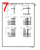
11 / 24 page  Functional Description (Continued) SLOPE COMPENSATION RAMP The LM3488 uses a current mode control scheme. The main advantages of current mode control are inherent cycle-by- cycle current limit for the switch, and simpler control loop characteristics. It is also easy to parallel power stages using current mode control since as current sharing is automatic. Current mode control has an inherent instability for duty cycles greater than 50%, as shown in Figure 2.In Figure 2, a small increase in the load current causes the switch cur- rent to increase by ∆I O. The effect of this load change, ∆I 1,is : From the above equation, when D > 0.5, ∆I 1 will be greater than ∆I O. In other words, the disturbance is divergent. So a very small perturbation in the load will cause the disturbance to increase. To prevent the sub-harmonic oscillations, a compensation ramp is added to the control signal, as shown in Figure 3. With the compensation ramp, 10138807 FIGURE 1. Basic Operation of the PWM comparator 10138809 FIGURE 2. Sub-Harmonic Oscillation for D>0.5 www.national.com 11 |
|
|
Link URL |
| War ALLDATASHEET hilfreich? [ DONATE ] |
Über Alldatasheet | Werbung | Kontakt | Privatsphäre und Datenschutz | Link zum Datenblatt | Linktausch | Hersteller All Rights Reserved©Alldatasheet.com |
| Russian : Alldatasheetru.com | Korean : Alldatasheet.co.kr | Spanish : Alldatasheet.es | French : Alldatasheet.fr | Italian : Alldatasheetit.com Portuguese : Alldatasheetpt.com | Polish : Alldatasheet.pl | Vietnamese : Alldatasheet.vn Indian : Alldatasheet.in | Mexican : Alldatasheet.com.mx | British : Alldatasheet.co.uk | New Zealand : Alldatasheet.co.nz |
|
Family Site : ic2ic.com |
icmetro.com |
 German ▼
 English
 Chinese
 German
 Japanese
 Russian
 Korean
 Spanish
 French
 Italian
 Portuguese
 Polish
 Vietnamese
 Indian
 Mexican
 British
 New Zealand