|
Datenblatt-Suchmaschine für elektronische Bauteile |
|
|
Datenblatt-Suchmaschine für elektronische Bauteile |
|
SD42524 Datenblatt(PDF) 4 Page - Silan Microelectronics Joint-stock |
|
|
|||||||||||||||||||||||||||||
SD42524 Datenblatt(HTML) 4 Page - Silan Microelectronics Joint-stock |
|
|
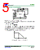
4 / 11 page  SD42524 amplifier output; and the current comparator’s output is low. The rising edge of the 280KHz CLK signal sets the RS Flip-Flop whose output turns on M1 thus VIN, Rs, LED, inductor and M1 comprises a circuit loop and the inductor current increases. The inductor current is sensed and amplified by the current sense amplifier. Ramp compensation is summed to current sense amplifier output and compared to the Gm amplifier output by the current comparator. When the current sense amplifier plus ramp compensation signal exceeds the comp pin voltage, the RS Flip-Flop is reset and the chip reverts to its initial M1 off state. The inductor energy storage released via the circuit loop composed by Rs, LED, inductor and M1 and the current decreases. When next clock cycle arrives, the upper transistor M1 is on to enter next switch cycle. If the current sense amplifier plus slope compensation signal does not exceed the comp voltage in one cycle, then the falling edge of the CLK resets the Flip-Flop. The Gm amplifier compares the output current with the threshold current (threshold current is set by internal). When the output current is higher than threshold current, the COMP pin’s voltage is lower down. Since the COMP pin’s voltage is proportional to the peak inductor current a decrease in its voltage decreases current delivered to the output. When the output current is lower than threshold current, the COMP pin’s voltage is up while the output current increases. The output current is stable at the set value by adjusting the circuit loop. 1. PWM dimming function SD42524 has internal PWM dimming function. When PWM voltage is connects to high level, the chip is working normally; when PWM voltage is open or connects to low level, COMP pin disconnects with the chip, the charge of the capacitor is in hold state, voltage level holds, and the output of current comparator is high, transistor is off without output current. When PWM signal is high, COMP pin is connected with the chip to improve the startup speed of the chip. Adjust the output current by control the duty of external PWM signal. The minimum setup time of SD42524 PWM dimming is less than 20 μS, and the maximum PWM dimming ratio is up to 500:1. When high dimming ratio is needed, the dimming frequency is recommended 500Hz below; or else the dimming frequency can be up to 2 KHz. When PWM pin is low, output is shutdown. In normal station, LED pin holds above 2V, and if the LED or other components have electric leakage which makes the LED pin is low and caused change on PWM dimming, the output capacitor is recommend to be increased, then the LED level will not be too low when shutdown to maintain the normal PWM dimming. 2. Output current setting The output current is determined by the sampling resistor and setting voltage. The sampling voltage of VIN- VSENSE(Drop voltage on Rs) is 88mV, and adjust the output current by adjusting the sampling resistor Rs (refer to Typical Application Circuit). S SENSE IN OUT R V V I − = 3. Current limiting SD42524 has internal current limiting function, and the voltage on COMP is clamped at about 1.9V, the output current of the power MOSFET is limited at about 1.9A by current comparator. 4. Frequency jitter SD42524 has internal frequency jitter function to improve the EMI performance of the system. The internal frequency is hopping in a very small range to reduce the single frequency radiation which simplifies the EMI design. HANGZHOU SILAN MICROELECTRONICS CO.,LTD REV:1.1 2009.06.26 Http://www.silan.com.cn Page 4 of 11 |
|
|
Link URL |
| War ALLDATASHEET hilfreich? [ DONATE ] |
Über Alldatasheet | Werbung | Kontakt | Privatsphäre und Datenschutz | Link zum Datenblatt | Linktausch | Hersteller All Rights Reserved©Alldatasheet.com |
| Russian : Alldatasheetru.com | Korean : Alldatasheet.co.kr | Spanish : Alldatasheet.es | French : Alldatasheet.fr | Italian : Alldatasheetit.com Portuguese : Alldatasheetpt.com | Polish : Alldatasheet.pl | Vietnamese : Alldatasheet.vn Indian : Alldatasheet.in | Mexican : Alldatasheet.com.mx | British : Alldatasheet.co.uk | New Zealand : Alldatasheet.co.nz |
|
Family Site : ic2ic.com |
icmetro.com |
 German ▼
 English
 Chinese
 German
 Japanese
 Russian
 Korean
 Spanish
 French
 Italian
 Portuguese
 Polish
 Vietnamese
 Indian
 Mexican
 British
 New Zealand