|
Datenblatt-Suchmaschine für elektronische Bauteile |
|
|
Datenblatt-Suchmaschine für elektronische Bauteile |
|
PI3USB102ZLE Datenblatt(PDF) 3 Page - Pericom Semiconductor Corporation |
|
|
|||||||||||||||||||||||||||||
PI3USB102ZLE Datenblatt(HTML) 3 Page - Pericom Semiconductor Corporation |
|
|
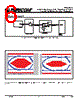
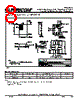
3 / 8 page  3 PI3USB102 USB 2.0 High-Speed (480 Mbps) Signal Switch Targeted for Battery Powered Applications PS8950C 11/20/08 Capacitance (TA = 25°C, f = 1MHz) Parameters(3) Description Test Conditions(1) Typ.(2) Max. Units CIN Input Capacitance VSEL = 0V 2.2 3.2 pF COFF Switch Capacitance, Switch OFF 2.4 3.4 CON Switch Capacitance, Switch ON 5.5 7.0 Notes: 1. For max. or min. conditions, use appropriate value specified under Electrical Characteristics for the applicable device type. 2. Typical values are at VDD = 3.3V, TA = 25°C ambient and maximum loading. 3. This parameter is determined by device characterization but is not production tested. Dynamic Electrical Characteristics Over the Operating Range Parameters Description Test Conditions Min. Typ.(2) Max. Units XTALK Crosstalk RL = 50Ω, f = 240 MHz –35 dB OIRR OFF Isolation –40 BW –3dB Bandwidth RL = 50Ω 810 MHz BW –0.5dB Bandwidth RL = 50Ω 300 MHz Switching Characteristics Parameters Description Test Conditions (1) Min. Typ. Max. Units tPD Propagation Delay(2,3) See Test Circuit for Electrical Charac- teristics 0.25 ns tPZH, tPZL Line Enable Time - SEL, OE to D(+/-), M(+/-) 0.5 50 tPHZ, tPLZ Line Disable Time - SEL, OE to D(+/-), M(+/-) 0.5 9.0 tSKC-C Output skew, channel-to-channel(2) 3.5 14 ps tSKb-b Output skew, bit-to-bit (opposite transition of the same output (tPHL-tPLH)(2) 7.5 20 Notes: 1. For max. or min. conditions, use appropriate value specified under Electrical Characteristics for the applicable device type. 2. Guaranteed by design. 3. The switch contributes no propagational delay other than the RC delay of the On-Resistance of the switch and the load capacitance. The time constant for the switch alone is of the order of 0.25ns for 10pF load. Since this time constant is much smaller than the rise/fall times of typical driving signals, it adds very little propagational delay to the system. Propagational delay of the switch when used in a system is determined by the driving circuit on the driving side of the switch and its interactions with the load on the driven side. 08-0310 |
|
|
Link URL |
| War ALLDATASHEET hilfreich? [ DONATE ] |
Über Alldatasheet | Werbung | Kontakt | Privatsphäre und Datenschutz | Link zum Datenblatt | Linktausch | Hersteller All Rights Reserved©Alldatasheet.com |
| Russian : Alldatasheetru.com | Korean : Alldatasheet.co.kr | Spanish : Alldatasheet.es | French : Alldatasheet.fr | Italian : Alldatasheetit.com Portuguese : Alldatasheetpt.com | Polish : Alldatasheet.pl | Vietnamese : Alldatasheet.vn Indian : Alldatasheet.in | Mexican : Alldatasheet.com.mx | British : Alldatasheet.co.uk | New Zealand : Alldatasheet.co.nz |
|
Family Site : ic2ic.com |
icmetro.com |
 German ▼
 English
 Chinese
 German
 Japanese
 Russian
 Korean
 Spanish
 French
 Italian
 Portuguese
 Polish
 Vietnamese
 Indian
 Mexican
 British
 New Zealand