 |
Datenblatt-Suchmaschine für elektronische Bauteile |
|
|
Datenblatt-Suchmaschine für elektronische Bauteile |
|
The question interval is too short.
Please try again in a few seconds.

Hello, Please ask a question about PIC12F510 Datasheet
# Example questions:
➢ Explain the clocking scheme used in the pic12f510/16f506 microcontrollers. specifically, how are the quadrature clocks (q1-q4) generated and utilized?
➢ Describe the concept of instruction pipelining as it applies to the pic12f510/16f506. how does pipelining affect the execution time of instructions, and what happens when a branch instruction (like goto) is encountered?
➢ What are the key differences between the clock/instruction cycle for a typical instruction versus an instruction that causes a change in the program counter (pc)?
| Part No. | PIC12F510 |
| Manufacturer | MICROCHIP |
| Size | 1Mb |
| Pages | 124 pages |
| Description | 8/14-Pin, 8-Bit Flash Microcontrollers |








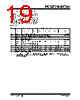


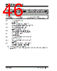
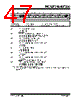





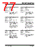








Okay, let's break down the information provided in the text. Here's a summary of the key points about the PIC12F506 and PIC16F506 microcontrollers:
1. Serial Programming Interface:
️· RB0/AN0/C1IN+/ICSPDAT (PIC16F506) and RB1/AN1/C1IN-/ICSPCLK (PIC16F506): These pins are used for In-Circuit Serial Programming (ICSP). RB0 acts as data, and RB1 as the clock.
2. Pin Functions and Key Features:
️· Oscillator Inputs/Outputs: OSC1/CLKIN and OSC2 pins are used for the crystal oscillator circuit. The clock input is divided internally by 4 to generate four quadrature clocks (Q1, Q2, Q3, Q4).
️· Analog Inputs: Pins like AN0, AN1, AN2 are configured as analog input pins for the ADC (Analog-to-Digital Converter).
️· Comparators: Comparators are available with dedicated input pins (e.g., C1IN+, C1IN-, C2IN+, C2IN-) and output pins (C1OUT, C2OUT). They compare analog voltages.
️· Voltage Reference: RC2 can be used as a programmable voltage reference output.
️· Timer Input: RC5, for example, is the Timer0 clock input (T0CKI).
️· Instruction Pipelining: The microcontrollers use pipelining to improve instruction execution speed. The fetch and execute stages are overlapped, allowing subsequent instructions to be fetched while the current one is being executed. This effectively reduces the overall execution time per instruction.
️· Clock Scheme: The PIC16F506 internally divides the oscillator frequency by 4.
3. Key Differences Between the PIC12F506 and PIC16F506:
While both devices share many core functions, they have distinct pin configurations and features. For example:
️· PIC12F506 uses RB0 and RB1 as data and clock for ICSP.
️· PIC16F506 uses RC0,RC1,RC2,RC3,RC4,RC5, and RB4 as I/O pins in addition to the aforementioned pins.
Overall, this documentation provides a basic overview of the microcontroller's architecture, pin functions, and key features, with a focus on serial programming and instruction execution.
1. Serial Programming Interface:
️· RB0/AN0/C1IN+/ICSPDAT (PIC16F506) and RB1/AN1/C1IN-/ICSPCLK (PIC16F506): These pins are used for In-Circuit Serial Programming (ICSP). RB0 acts as data, and RB1 as the clock.
2. Pin Functions and Key Features:
️· Oscillator Inputs/Outputs: OSC1/CLKIN and OSC2 pins are used for the crystal oscillator circuit. The clock input is divided internally by 4 to generate four quadrature clocks (Q1, Q2, Q3, Q4).
️· Analog Inputs: Pins like AN0, AN1, AN2 are configured as analog input pins for the ADC (Analog-to-Digital Converter).
️· Comparators: Comparators are available with dedicated input pins (e.g., C1IN+, C1IN-, C2IN+, C2IN-) and output pins (C1OUT, C2OUT). They compare analog voltages.
️· Voltage Reference: RC2 can be used as a programmable voltage reference output.
️· Timer Input: RC5, for example, is the Timer0 clock input (T0CKI).
️· Instruction Pipelining: The microcontrollers use pipelining to improve instruction execution speed. The fetch and execute stages are overlapped, allowing subsequent instructions to be fetched while the current one is being executed. This effectively reduces the overall execution time per instruction.
️· Clock Scheme: The PIC16F506 internally divides the oscillator frequency by 4.
3. Key Differences Between the PIC12F506 and PIC16F506:
While both devices share many core functions, they have distinct pin configurations and features. For example:
️· PIC12F506 uses RB0 and RB1 as data and clock for ICSP.
️· PIC16F506 uses RC0,RC1,RC2,RC3,RC4,RC5, and RB4 as I/O pins in addition to the aforementioned pins.
Overall, this documentation provides a basic overview of the microcontroller's architecture, pin functions, and key features, with a focus on serial programming and instruction execution.
| Part No. | PIC12F510 |
| Manufacturer | MICROCHIP |
| Size | 1Mb |
| Pages | 124 pages |
| Description | 8/14-Pin, 8-Bit Flash Microcontrollers |
| War ALLDATASHEET hilfreich? [ DONATE ] |
Über Alldatasheet | Werbung | Kontakt | Privatsphäre und Datenschutz | Link zum Datenblatt | Linktausch | Hersteller All Rights Reserved©Alldatasheet.com |
| Russian : Alldatasheetru.com | Korean : Alldatasheet.co.kr | Spanish : Alldatasheet.es | French : Alldatasheet.fr | Italian : Alldatasheetit.com Portuguese : Alldatasheetpt.com | Polish : Alldatasheet.pl | Vietnamese : Alldatasheet.vn Indian : Alldatasheet.in | Mexican : Alldatasheet.com.mx | British : Alldatasheet.co.uk | New Zealand : Alldatasheet.co.nz |
|
Family Site : ic2ic.com |
icmetro.com |
 German ▼
  English
 Chinese
 Japanese
 Russian
 Korean
 Spanish
 French
 Italian
 Portuguese
 Polish
 Vietnamese
 Indian
 Mexican
 British
 New Zealand