|
Datenblatt-Suchmaschine für elektronische Bauteile |
|
|
Datenblatt-Suchmaschine für elektronische Bauteile |
|
EV-RADAR-MMIC Datenblatt(PDF) 5 Page - Analog Devices |
|
|
|||||||||||||||||||||||||||||
EV-RADAR-MMIC Datenblatt(HTML) 5 Page - Analog Devices |
|
|
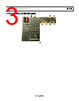
5 / 28 page  EV-RADAR-MMIC2 User Guide UG-866 Rev. B | Page 5 of 28 EVALUATION BOARD HARDWARE The EV-RADAR-MMIC2 evaluation board requires an SDP-S or SDP-B motherboard to program the device. These SDP boards are not included with the evaluation board and must be purchased separately. POWER SUPPLIES The EV-RADAR-MMIC2 evaluation board is powered via one external supply of 5 V connected to VSUPPLY as described in the Quick Start Guide section. The EV-ADAR-D2S board is powered via two external supplies: +9 V connected to VPOS and −9 V connected to VNEG, as described in the Quick Start Guide section. INPUT SIGNALS The on-board, 100 MHz temperature compensated crystal oscillator (TCXO) provides the necessary reference signal. Use an external REFIN signal, if desired. RADIO FREQUENCY (RF) INPUT SIGNALS The RF input pins on the ADF5904 contain a dc bias voltage and must be ac-coupled to the EV-RADAR-MMIC2 evaluation board. The RF inputs are on the J2 (RX1_RFIN), J3 (RX2_RFIN), J4 (RX3_RFIN), and J6 (RX4_RFIN) SMA connectors. RF OUTPUT SIGNALS The Tx outputs from the ADF5901 contain a dc bias voltage and must be ac-coupled. The Tx outputs are available on the J8 (TX_OUT1) and J9 (TX_OUT2) output SMA connectors. CHANNEL MAPPING Table 1 shows the pin mapping from the ADF5904 RXx_xx to baseband outputs on the EV-ADAR-D2S evaluation board. Table 1. Pin Mapping EV-RADAR-MMIC2 Connector ADF5904 Input EV-ADAR-D2S Connector J2 RX1_RFIN O7 J3 RX2_RFIN O8 J4 RX3_RFIN O6 J6 RX4_RFIN O5 DEFAULT OPERATION All components necessary for operation are inserted on the board. |
|
Link URL |
| War ALLDATASHEET hilfreich? [ DONATE ] |
Über Alldatasheet | Werbung | Kontakt | Privatsphäre und Datenschutz | Link zum Datenblatt | Linktausch | Hersteller All Rights Reserved©Alldatasheet.com |
| Russian : Alldatasheetru.com | Korean : Alldatasheet.co.kr | Spanish : Alldatasheet.es | French : Alldatasheet.fr | Italian : Alldatasheetit.com Portuguese : Alldatasheetpt.com | Polish : Alldatasheet.pl | Vietnamese : Alldatasheet.vn Indian : Alldatasheet.in | Mexican : Alldatasheet.com.mx | British : Alldatasheet.co.uk | New Zealand : Alldatasheet.co.nz |
|
Family Site : ic2ic.com |
icmetro.com |
 German ▼
 English
 Chinese
 German
 Japanese
 Russian
 Korean
 Spanish
 French
 Italian
 Portuguese
 Polish
 Vietnamese
 Indian
 Mexican
 British
 New Zealand