|
Datenblatt-Suchmaschine für elektronische Bauteile |
|
|
Datenblatt-Suchmaschine für elektronische Bauteile |
|
E39-R1 Datenblatt(PDF) 25 Page - Omron Electronics LLC |
|
|
|||||||||||||||||||||||||||||
E39-R1 Datenblatt(HTML) 25 Page - Omron Electronics LLC |
|
|
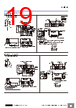
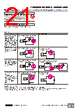
25 / 27 page  Photoelectric Sensors Technical Guide Securing Fibers The E3X Fiber Unit uses a one-touch locking mechanism. Use the following methods to attach and remove Fiber Units. (1) Attaching Fibers Open the protective cover, insert the fiber up to the insertion mark on the side of the Fiber Unit, and then lower the lock lever. (2) Removing Fibers Open the protective cover, lift up the lock lever, and pull out the fibers. ● Adjustments Optical Axis Adjustment Move the Photoelectric Sensor both vertically and horizontally and set it in the center of the range in which the operation indicator is lit or not lit. For the E3S-C, the optical axis and the mechanical axis are the same, so the optical axis can be easily adjusted by aligning the mechanical axis. Optical axis: The axis from the center of the lens to the center of the beam for the Emitter and the axis from the center of the lens to the center of the reception area for the Receiver. Mechanical axis: The axis perpendicular to the center of the lens. Note:1.To maintain the fiber characteristics, make sure that the lock is released before removing the fibers. 2. Lock and unlock the fibers at an ambient temperature of −10 to 40°C. 9mm Insertion position Locked position Lock released position Protective cover Lock lever Fiber insertion mark Fiber Locked position Lock released position Protective cover l 1 2 Emitter Receiver Incident indicator or Operation indicator ON OFF Incident indicator or Operation indicator Optimum value ON OFF Emitter Receiver Emission beam Optical axis Optical axis Mechanical axis Reception area http://www.ia.omron.com/ C-5 (c)Copyright OMRON Corporation 2007 All Rights Reserved. |
|
Link URL |
| War ALLDATASHEET hilfreich? [ DONATE ] |
Über Alldatasheet | Werbung | Kontakt | Privatsphäre und Datenschutz | Link zum Datenblatt | Linktausch | Hersteller All Rights Reserved©Alldatasheet.com |
| Russian : Alldatasheetru.com | Korean : Alldatasheet.co.kr | Spanish : Alldatasheet.es | French : Alldatasheet.fr | Italian : Alldatasheetit.com Portuguese : Alldatasheetpt.com | Polish : Alldatasheet.pl | Vietnamese : Alldatasheet.vn Indian : Alldatasheet.in | Mexican : Alldatasheet.com.mx | British : Alldatasheet.co.uk | New Zealand : Alldatasheet.co.nz |
|
Family Site : ic2ic.com |
icmetro.com |
 German ▼
 English
 Chinese
 German
 Japanese
 Russian
 Korean
 Spanish
 French
 Italian
 Portuguese
 Polish
 Vietnamese
 Indian
 Mexican
 British
 New Zealand