|
Datenblatt-Suchmaschine für elektronische Bauteile |
|
|
Datenblatt-Suchmaschine für elektronische Bauteile |
|
LM3477 Datenblatt(PDF) 12 Page - National Semiconductor (TI) |
|
|
|
|||||||||||||||||||||||||||||
LM3477 Datenblatt(HTML) 12 Page - National Semiconductor (TI) |
|
|
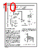
12 / 23 page  Functional Description (Continued) Default/Adjustable Slope Compensation The LM3477/A uses a current mode control scheme. There are many advantages in a current mode architecture includ- ing inherent cycle-by-cycle current limiting and simple com- pensation of the control loop. However, there are conse- quences to using current mode control that one must be aware of while selecting circuit components. One of these consequences is the inherent possibility of subharmonic os- cillations in the inductor current. This is a form of instability and should be avoided. As a brief explanation, consider Figure 4. A lot of information is shown here. The top portion shows a schematic of the current sensing loop. The bottom portion shows the pulse width modulation (PWM) comparator waveforms for two switching cycles. The two solid waveforms shown are the waveforms compared at the internal pulse width modulator, used to generate the MOSFET drive signal. The top wave- form with the slope S e is the internally generated control waveform V C. The bottom waveform with slopes Sn and Sf is the sensed inductor current waveform V SEN. These signals are compared at the PWM comparator. There is a feedback loop involved here. The inductor current is sensed and fed back to the PWM comparator, where it is compared to V C. The output of the comparator in combination with the R/S latch determine if the MOSFET is on or off, which effectively controls the amount of current the inductor receives. While V C is higher than VSEN, the PWM comparator outputs a high signal, driving the external power MOSFET on. When MOS- FET is on, the inductor current rises at a constant slope, generating the sensed voltage V SEN. When VSEN equals VC, the PWM comparator signals to drive the MOSFET off, and the sensed inductor current decreases with a slope S f. The process begins again when R S latch is set by an internal oscillator. The subharmonic oscillation phenomenon is realized when a load excursion is experienced. The way it is analyzed is to calculate how the inductor current settles after such an excursion. Take for example the case when the inductor current experiences a step increase in its average current, shown as the dotted line in Figure 4. In the switching period that the excursion occurs, the inductor current will change by ∆I 0. In the following switching period, the inductor current will have a difference ∆I 1 from its original starting value. The original excursion is being propagated each switching cycle. What is desired is to find out if this propagation is converging or diverging. It is apparent that the difference in the inductor current from one cycle to the next is a function of S n,Sf, and S e, as follows: Hence, if the quantity (S f -Se)/(Sn +Se)is greater than 1, the inductor current diverges and subharmonic oscillations re- sult. Notice that as S e increases, the factor decreases. Also, when the duty cycle is greater than 50%, as the inductance become less, the factor increases. The LM3477/A internally generates enough slope compen- sation S e to allow for the use of reasonable inductances. The height of the compensation slope ramp V SL can be found in the ELECTRICAL CHARACTERISTICS section. The LM3477/A incorporates a patented scheme to increase S e if there is need to use a smaller inductor. With the use of a single resistor R SL, Se can be increased indefinitely. RSL increases the compensation slope Se by the amount: Therefore, When excursions of the inductor current are divergent, the current sensing control loop is unstable and produces a subharmonic oscillation in the inductor current. This oscilla- tion is viewed as a resonance in the outer voltage control loop at half the switching frequency. In the inductor section, 200033J6 FIGURE 3. The Feedback Voltage Experiences an Oscillation if the Input Voltage Crosses the 7.2V Internal Bias Threshold 200033C2 FIGURE 4. The Current Sensing Loop and Corresponding Waveforms www.national.com 12 |
|
|
Link URL |
| War ALLDATASHEET hilfreich? [ DONATE ] |
Über Alldatasheet | Werbung | Kontakt | Privatsphäre und Datenschutz | Link zum Datenblatt | Linktausch | Hersteller All Rights Reserved©Alldatasheet.com |
| Russian : Alldatasheetru.com | Korean : Alldatasheet.co.kr | Spanish : Alldatasheet.es | French : Alldatasheet.fr | Italian : Alldatasheetit.com Portuguese : Alldatasheetpt.com | Polish : Alldatasheet.pl | Vietnamese : Alldatasheet.vn Indian : Alldatasheet.in | Mexican : Alldatasheet.com.mx | British : Alldatasheet.co.uk | New Zealand : Alldatasheet.co.nz |
|
Family Site : ic2ic.com |
icmetro.com |
 German ▼
 English
 Chinese
 German
 Japanese
 Russian
 Korean
 Spanish
 French
 Italian
 Portuguese
 Polish
 Vietnamese
 Indian
 Mexican
 British
 New Zealand