|
Datenblatt-Suchmaschine für elektronische Bauteile |
|
|
Datenblatt-Suchmaschine für elektronische Bauteile |
|
AD8275ARMZ-R7 Datenblatt(PDF) 15 Page - Analog Devices |
|
|
|||||||||||||||||||||||||||||
AD8275ARMZ-R7 Datenblatt(HTML) 15 Page - Analog Devices |
|
|
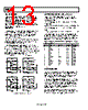
15 / 17 page  AD8275 Rev. A | Page 14 of 16 APPLICATIONS INFORMATION DRIVING A SINGLE-ENDED ADC The AD8275 provides the common-mode rejection that SAR ADCs often lack. In addition, it enables designers to use cost- effective, precision, 16-bit ADCs such as the AD7685, yet still condition ±10 V signals. One important factor in selecting an ADC driver is its ability to settle within the acquisition window of the ADC. The AD8275 is able to drive medium speed SAR ADCs. In Figure 38, the 2.7 nF capacitor serves to store and deliver necessary charge to the switched capacitor input of the ADC. The 33 Ω series resistor reduces the burden of the 2.7 nF load from the amplifier and isolates it from the kickback current injected from the switched capacitor input of the AD7685. The output impedance of the amplifier can affect the THD of the ADC. In this case, the combined impedance of the 33 Ω resistor and the output impedance of the AD8275 provides extremely low THD of −112 dB. Figure 39 shows the ac response of the AD8275 driving the AD7685. VREF (ADR444, ADR445) AD8275 7 4 5 6 8 2 50k Ω 0.1µF 50k Ω 20k Ω 20k Ω 33 Ω 10k Ω 3 +IN –IN VIN REF2 REF1 –VS +VS +5V OUT SENSE 0.1µF 2.7nF 10µF 1 AD7685 VDD GND REF IN+ IN– Figure 38. Driving a Single-Ended ADC 10 0 –10 –20 –30 –40 –50 –60 –70 –80 –90 –100 –110 –120 –130 –140 –150 –160 –170 0 1 4 7 10 FREQUENCY (kHz) 2 5 8 3 6 9 Figure 39. FFT of AD8275 Directly Driving the AD7685 Using the 5 V Reference of the Evaluation Board (Input = 20 V p-p, 1 kHz, THD = −112 dB) The AD8275 can condition signals for higher resolution ADCs such as 18-bit SAR converters, provided that a narrower bandwidth is sampled to limit noise. DIFFERENTIAL OUTPUTS In certain applications, it is necessary to create a differential signal. For example, high resolution ADCs often require a differential input. In other cases, transmission over a long distance can require differential signals for better immunity to interference. Figure 40 shows how to configure the AD8275 to output a differential signal. The AD8655 op amp is used in an inverting topology to create a differential voltage. VREF sets the output midpoint. Errors from the op amp are common to both outputs and are thus common mode. Likewise, errors from using mismatched resistors cause a common-mode dc offset error. Such errors are rejected in differential signal processing by differential input ADCs or by instrumentation amplifiers. When using this circuit to drive a differential ADC, VREF can be set using a resistor divider from the ADC reference to make the output ratiometric with the ADC. AD8275 7 4 5 6 8 2 50k Ω 0.1µF 0.1µF 8.2µF 50k Ω 20k Ω 20k Ω 2k Ω 2k Ω 10k Ω 3 +IN –IN REF2 REF1 –VS +VS +5V +10V –10V +5V OUT SENSE 1 AD8655 VREF = 2.5V +VOUT –VOUT +3.5V +1.5V +2.5V +3.5V +1.5V +2.5V Figure 40. AD8275 Configured for Differential Output (for Driving a Differential ADC) |
|
|
Link URL |
| War ALLDATASHEET hilfreich? [ DONATE ] |
Über Alldatasheet | Werbung | Kontakt | Privatsphäre und Datenschutz | Link zum Datenblatt | Linktausch | Hersteller All Rights Reserved©Alldatasheet.com |
| Russian : Alldatasheetru.com | Korean : Alldatasheet.co.kr | Spanish : Alldatasheet.es | French : Alldatasheet.fr | Italian : Alldatasheetit.com Portuguese : Alldatasheetpt.com | Polish : Alldatasheet.pl | Vietnamese : Alldatasheet.vn Indian : Alldatasheet.in | Mexican : Alldatasheet.com.mx | British : Alldatasheet.co.uk | New Zealand : Alldatasheet.co.nz |
|
Family Site : ic2ic.com |
icmetro.com |
 German ▼
 English
 Chinese
 German
 Japanese
 Russian
 Korean
 Spanish
 French
 Italian
 Portuguese
 Polish
 Vietnamese
 Indian
 Mexican
 British
 New Zealand