 |
Datenblatt-Suchmaschine für elektronische Bauteile |
|
|
Datenblatt-Suchmaschine für elektronische Bauteile |
|
The question interval is too short.
Please try again in a few seconds.

Hello, Please ask a question about M24256E-F Datasheet
# Example questions:
➢ What must be true for the device to acknowledge a write command to the configurable device address register when c2, c1, and c0 are being re-configured?
➢ Explain the purpose of the ecc (error correction code) and how it functions within the m2456-dr device.
➢ Describe the process of 'polling' during a write operation and what the device's response (ack or noack) indicates to the bus master.
| Part No. | M24256E-F |
| Manufacturer | STMICROELECTRONICS |
| Size | 864 Kbytes |
| Pages | 46 pages |
| Description | 256-Kbit serial I2C bus EEPROM with configurable device address |

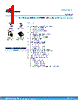

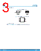


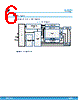
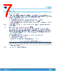
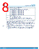

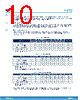



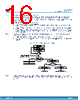

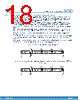

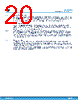


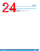


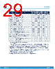







Okay, here's a summary of the key points from the provided text, focusing on the information relevant to understanding the device's operation and write capabilities. I've organized it for clarity.
1. Core Functionality: EEPROM with I2C Interface
️· The device is an EEPROM (Electrically Erasable Programmable Read-Only Memory) that communicates via the I2C protocol.
️· It has a standard memory array and a separate Identification Page.
2. Writing to Memory
️· Byte Write: Writes a single byte.
️· Page Write: Writes up to 64 bytes in a single operation, *if* they are within the same page of memory. If you exceed the page boundary, the write "rolls over" to the beginning of the page.
️· Write Control (WC): A pin or signal. If HIGH, writing to a location is inhibited (no acknowledgement).
️· ECC: Error Correction Code is implemented internally, improving reliability. Writes can affect multiple bytes due to ECC.
️· Write Cycle & Polling: You can check if a write is complete by sending a start condition and device select code. If the device is busy, it won't acknowledge. This allows for faster operation.
3. Identification Page
️· A separate 64-byte area for storing identification information.
️· Write Identification Page: Uses a similar protocol to the page write to memory array.
️· Lock Identification Page: Permanently locks the identification page in read-only mode. Requires sending a specific data byte with bit 1 set to '1'.
4. Addressing
️· Different address ranges are used for the main memory array and the Identification Page. Refer to Section 5.5 and Tables 3, 4, and 5 for the correct addressing scheme.
5. Important Write Considerations
️· Acknowledgement (ACK/No ACK): The device uses ACK/No ACK signals to indicate success or failure of write operations.
️· Write Delays: Write operations take time. Polling on ACK/No ACK can reduce wait times.
️· Configuration of Chip Enable address (C2, C1, C0) : If you re-configure the chip enable address, the device acknowledges write operations *only* if the new chip enable address is correct, and the internal write cycle is completed.
Let me know if you'd like a deeper dive into any specific aspect, or if you have any particular questions about the device’s operation.
1. Core Functionality: EEPROM with I2C Interface
️· The device is an EEPROM (Electrically Erasable Programmable Read-Only Memory) that communicates via the I2C protocol.
️· It has a standard memory array and a separate Identification Page.
2. Writing to Memory
️· Byte Write: Writes a single byte.
️· Page Write: Writes up to 64 bytes in a single operation, *if* they are within the same page of memory. If you exceed the page boundary, the write "rolls over" to the beginning of the page.
️· Write Control (WC): A pin or signal. If HIGH, writing to a location is inhibited (no acknowledgement).
️· ECC: Error Correction Code is implemented internally, improving reliability. Writes can affect multiple bytes due to ECC.
️· Write Cycle & Polling: You can check if a write is complete by sending a start condition and device select code. If the device is busy, it won't acknowledge. This allows for faster operation.
3. Identification Page
️· A separate 64-byte area for storing identification information.
️· Write Identification Page: Uses a similar protocol to the page write to memory array.
️· Lock Identification Page: Permanently locks the identification page in read-only mode. Requires sending a specific data byte with bit 1 set to '1'.
4. Addressing
️· Different address ranges are used for the main memory array and the Identification Page. Refer to Section 5.5 and Tables 3, 4, and 5 for the correct addressing scheme.
5. Important Write Considerations
️· Acknowledgement (ACK/No ACK): The device uses ACK/No ACK signals to indicate success or failure of write operations.
️· Write Delays: Write operations take time. Polling on ACK/No ACK can reduce wait times.
️· Configuration of Chip Enable address (C2, C1, C0) : If you re-configure the chip enable address, the device acknowledges write operations *only* if the new chip enable address is correct, and the internal write cycle is completed.
| Part No. | M24256E-F |
| Manufacturer | STMICROELECTRONICS |
| Size | 864 Kbytes |
| Pages | 46 pages |
| Description | 256-Kbit serial I2C bus EEPROM with configurable device address |
| War ALLDATASHEET hilfreich? [ DONATE ] |
Über Alldatasheet | Werbung | Kontakt | Privatsphäre und Datenschutz | Link zum Datenblatt | Linktausch | Hersteller All Rights Reserved©Alldatasheet.com |
| Russian : Alldatasheetru.com | Korean : Alldatasheet.co.kr | Spanish : Alldatasheet.es | French : Alldatasheet.fr | Italian : Alldatasheetit.com Portuguese : Alldatasheetpt.com | Polish : Alldatasheet.pl | Vietnamese : Alldatasheet.vn Indian : Alldatasheet.in | Mexican : Alldatasheet.com.mx | British : Alldatasheet.co.uk | New Zealand : Alldatasheet.co.nz |
|
Family Site : ic2ic.com |
icmetro.com |
 German ▼
  English
 Chinese
 Japanese
 Russian
 Korean
 Spanish
 French
 Italian
 Portuguese
 Polish
 Vietnamese
 Indian
 Mexican
 British
 New Zealand