|
Datenblatt-Suchmaschine für elektronische Bauteile |
|
|
Datenblatt-Suchmaschine für elektronische Bauteile |
|
LTC2335-16 Datenblatt(PDF) 34 Page - Linear Technology |
|
|
|||||||||||||||||||||||||||||
LTC2335-16 Datenblatt(HTML) 34 Page - Linear Technology |
|
|
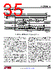
34 / 40 page  LTC2335-16 34 233516f For more information www.linear.com/LTC2335-16 applicaTions inForMaTion Eachdatatransactionwindowisanopportunitytoprogram thesequencerbyclockinginaseriesof8-bitcontrolwords on SDI, each specifying a channel number and SoftSpan range, as shown in Figures 17 and 18. To program the sequencer with a series of up to 16 conversion configu- rations, write in the corresponding control words in the desired conversion order during a single data transaction. Words beyond the 16th valid word will be ignored. The control word format is as follows: C[7] C[6] C[5] C[4] C[3] C[2] C[1] C[0] V 0 CH[2] CH[1] CH[0] SS[2] SS[1] SS[0] The V bit (C[7]) controls whether the LTC2335-16 should consider this a valid word. Any words which have V = 0 are considered invalid and are ignored (though valid words will still be accepted after an invalid word). Words which have V = 1 will be added to the sequencer in the order provided. The C[6] bit is reserved for future use and should be set to 0. The CH[2:0] (C[5:3]) bits are a binary value 0 to 7 controlling the channel to be converted. The SS[2:0] (C[2:0]) bits specify the desired SoftSpan range for the conversion, as described in Table 1. Sequencer programming is completed when the next conversion is started. At this time, any incomplete words are considered invalid and discarded. If one or more valid words were provided, the sequencer is completely overwritten with the new sequence, and the just-initiated conversion employs the first provided configuration. If no valid words were provided during the data transac- tion window, the sequencer program is unchanged, and the pointer advances to the next entry in the previously programmed cycle to configure the next conversion. Thus, once the sequencer has been programmed, simply hold SDI low during subsequent data transactions to cycle continually through the programmed sequence of configurations. Direct Per-Conversion Configuration As a special case of the sequencer, the LTC2335-16 multiplexer and SoftSpan range can be directly controlled every conversion with no latency and no additional set- tling time or digital I/O overhead. To use the part in this direct fashion, simply supply one control word on SDI during a data transaction to specify the desired channel number and SoftSpan range for the following conversion, as shown in Figure 17. If the desired channel and SoftSpan range for conversion N+1 are known before seeing the result of conversion N, specify the configuration by clocking in the corresponding control word on SDI while clocking out the first 8 bits, then hold SDI low. This particular use case is illustrated in Figure 17. If the desired configuration is not known until after the conversion data has been read, clock in 24 zeros on SDI while the 24 bits of data are being read out; since the V bits of those words are then 0, they are ignored. Once the configuration has been determined, clock in 8 more bits on SDI which specify the desired configuration for conversion N+1. Serial LVDS I/O Mode In LVDS I/O mode, information is transmitted using positive and negative signal pairs (LVDS+/LVDS−) with bits differentially encoded as (LVDS+ − LVDS−). These signals are typically routed using differential transmission lines with 100Ω characteristic impedance. Logical 1s and 0s are nominally represented by differential +350mV and −350mV,respectively.Forclarity,allLVDStimingdiagrams and interface discussions adopt the logical rather than physical convention. As shown in Figure 19, in LVDS I/O mode the serial data bus consists of a serial clock differential input, SCKI, serial data differential input, SDI, serial clock differential output, SCKO, and serial data differential output, SDO. Communi- cation with the LTC2335-16 across this bus occurs during predefined data transaction windows. Within a window, the device accepts control words on SDI to configure the SoftSpan range and channel for the next conversion and |
|
Link URL |
| War ALLDATASHEET hilfreich? [ DONATE ] |
Über Alldatasheet | Werbung | Kontakt | Privatsphäre und Datenschutz | Link zum Datenblatt | Linktausch | Hersteller All Rights Reserved©Alldatasheet.com |
| Russian : Alldatasheetru.com | Korean : Alldatasheet.co.kr | Spanish : Alldatasheet.es | French : Alldatasheet.fr | Italian : Alldatasheetit.com Portuguese : Alldatasheetpt.com | Polish : Alldatasheet.pl | Vietnamese : Alldatasheet.vn Indian : Alldatasheet.in | Mexican : Alldatasheet.com.mx | British : Alldatasheet.co.uk | New Zealand : Alldatasheet.co.nz |
|
Family Site : ic2ic.com |
icmetro.com |
 German ▼
 English
 Chinese
 German
 Japanese
 Russian
 Korean
 Spanish
 French
 Italian
 Portuguese
 Polish
 Vietnamese
 Indian
 Mexican
 British
 New Zealand