|
Datenblatt-Suchmaschine für elektronische Bauteile |
|
|
Datenblatt-Suchmaschine für elektronische Bauteile |
|
AT25DF321A-MH-T Datenblatt(PDF) 4 Page - ATMEL Corporation |
|
|
|||||||||||||||||||||||||||||
AT25DF321A-MH-T Datenblatt(HTML) 4 Page - ATMEL Corporation |
|
|
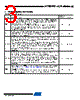
4 / 58 page  4 3686C–DFLASH–12/08 AT25DF321A [Preliminary] HOLD HOLD: The HOLD pin is used to temporarily pause serial communication without deselecting or resetting the device. While the HOLD pin is asserted, transitions on the SCK pin and data on the SI pin will be ignored, and the SO pin will be in a high-impedance state. The CS pin must be asserted, and the SCK pin must be in the low state in order for a Hold condition to start. A Hold condition pauses serial communication only and does not have an effect on internally self-timed operations such as a program or erase cycle. Please refer to “Hold” on page 46 for additional details on the Hold operation. The HOLD pin is internally pulled-high and may be left floating if the Hold function will not be used. However, it is recommended that the HOLD pin also be externally connected to VCC whenever possible. Low Input VCC DEVICE POWER SUPPLY: The VCC pin is used to supply the source voltage to the device. Operations at invalid V CC voltages may produce spurious results and should not be attempted. -Power GND GROUND: The ground reference for the power supply. GND should be connected to the system ground. -Power Figure 2-1. 8-SOIC (Top View) Figure 2-2. 8-UDFN (Top View) Table 2-1. Pin Descriptions (Continued) Symbol Name and Function Asserted State Type CS SO (SOI) WP GND 1 2 3 4 8 7 6 5 VCC HOLD SCK SI (SIO) CS SO (SOI) WP GND 1 2 3 4 8 7 6 5 VCC HOLD SCK SI (SIO) |
|
Link URL |
| War ALLDATASHEET hilfreich? [ DONATE ] |
Über Alldatasheet | Werbung | Kontakt | Privatsphäre und Datenschutz | Link zum Datenblatt | Linktausch | Hersteller All Rights Reserved©Alldatasheet.com |
| Russian : Alldatasheetru.com | Korean : Alldatasheet.co.kr | Spanish : Alldatasheet.es | French : Alldatasheet.fr | Italian : Alldatasheetit.com Portuguese : Alldatasheetpt.com | Polish : Alldatasheet.pl | Vietnamese : Alldatasheet.vn Indian : Alldatasheet.in | Mexican : Alldatasheet.com.mx | British : Alldatasheet.co.uk | New Zealand : Alldatasheet.co.nz |
|
Family Site : ic2ic.com |
icmetro.com |
 German ▼
 English
 Chinese
 German
 Japanese
 Russian
 Korean
 Spanish
 French
 Italian
 Portuguese
 Polish
 Vietnamese
 Indian
 Mexican
 British
 New Zealand