|
Datenblatt-Suchmaschine für elektronische Bauteile |
|
|
Datenblatt-Suchmaschine für elektronische Bauteile |
|
AT25DF321A-MH-Y Datenblatt(PDF) 3 Page - ATMEL Corporation |
|
|
|||||||||||||||||||||||||||||
AT25DF321A-MH-Y Datenblatt(HTML) 3 Page - ATMEL Corporation |
|
|
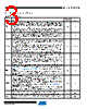
3 / 52 page  3 3686D–DFLASH–12/09 Atmel AT25DF321A 2. Pin Descriptions and Pinouts Table 2-1. Pin Descriptions Symbol Name and Function Asserted State Type CS CHIP SELECT: Asserting the CS pin selects the device. When the CS pin is deasserted, the device will be deselected and normally be placed in standby mode (not Deep Power-Down mode), and the SO pin will be in a high-impedance state. When the device is deselected, data will not be accepted on the SI pin. A high-to-low transition on the CS pin is required to start an operation, and a low-to-high transition is required to end an operation. When ending an internally self-timed operation such as a program or erase cycle, the device will not enter the standby mode until the completion of the operation. Low Input SCK SERIAL CLOCK: This pin is used to provide a clock to the device and is used to control the flow of data to and from the device. Command, address, and input data present on the SI pin is always latched in on the rising edge of SCK, while output data on the SO pin is always clocked out on the falling edge of SCK. - Input SI (SIO) SERIAL INPUT (SERIAL INPUT/OUTPUT): The SI pin is used to shift data into the device. The SI pin is used for all data input including command and address sequences. Data on the SI pin is always latched in on the rising edge of SCK. With the Dual-Output Read Array command, the SI pin becomes an output pin (SIO) to allow two bits of data (on the SO and SIO pins) to be clocked out on every falling edge of SCK. To maintain consistency with SPI nomenclature, the SIO pin will be referenced as SI throughout the document with exception to sections dealing with the Dual-Output Read Array command in which it will be referenced as SIO. Data present on the SI pin will be ignored whenever the device is deselected (CS is deasserted). - Input/Output SO (SOI) SERIAL OUTPUT (SERIAL OUTPUT/INPUT): The SO pin is used to shift data out from the device. Data on the SO pin is always clocked out on the falling edge of SCK. With the Dual-Input Byte/Page Program command, the SO pin becomes an input pin (SOI) to allow two bits of data (on the SOI and SI pins) to be clocked in on every rising edge of SCK. To maintain consistency with SPI nomenclature, the SOI pin will be referenced as SO throughout the document with exception to sections dealing with the Dual-Input Byte/Page Program command in which it will be referenced as SOI. The SO pin will be in a high-impedance state whenever the device is deselected (CS is deasserted). - Output/Input WP WRITE PROTECT: The WP pin controls the hardware locking feature of the device. Please refer to “Protection Commands and Features” on page 18 for more details on protection features and the WP pin. The WP pin is internally pulled-high and may be left floating if hardware controlled protection will not be used. However, it is recommended that the WP pin also be externally connected to V CC whenever possible. Low Input HOLD HOLD: The HOLD pin is used to temporarily pause serial communication without deselecting or resetting the device. While the HOLD pin is asserted, transitions on the SCK pin and data on the SI pin will be ignored, and the SO pin will be in a high-impedance state. The CS pin must be asserted, and the SCK pin must be in the low state in order for a Hold condition to start. A Hold condition pauses serial communication only and does not have an effect on internally self-timed operations such as a program or erase cycle. Please refer to “Hold” on page 40 for additional details on the Hold operation. The HOLD pin is internally pulled-high and may be left floating if the Hold function will not be used. However, it is recommended that the HOLD pin also be externally connected to V CC whenever possible. Low Input V CC DEVICE POWER SUPPLY: The V CC pin is used to supply the source voltage to the device. Operations at invalid V CC voltages may produce spurious results and should not be attempted. - Power GND GROUND: The ground reference for the power supply. GND should be connected to the system ground. - Power |
|
Link URL |
| War ALLDATASHEET hilfreich? [ DONATE ] |
Über Alldatasheet | Werbung | Kontakt | Privatsphäre und Datenschutz | Link zum Datenblatt | Linktausch | Hersteller All Rights Reserved©Alldatasheet.com |
| Russian : Alldatasheetru.com | Korean : Alldatasheet.co.kr | Spanish : Alldatasheet.es | French : Alldatasheet.fr | Italian : Alldatasheetit.com Portuguese : Alldatasheetpt.com | Polish : Alldatasheet.pl | Vietnamese : Alldatasheet.vn Indian : Alldatasheet.in | Mexican : Alldatasheet.com.mx | British : Alldatasheet.co.uk | New Zealand : Alldatasheet.co.nz |
|
Family Site : ic2ic.com |
icmetro.com |
 German ▼
 English
 Chinese
 German
 Japanese
 Russian
 Korean
 Spanish
 French
 Italian
 Portuguese
 Polish
 Vietnamese
 Indian
 Mexican
 British
 New Zealand