|
Datenblatt-Suchmaschine für elektronische Bauteile |
|
|
Datenblatt-Suchmaschine für elektronische Bauteile |
|
AT25DF321A-MH-Y Datenblatt(PDF) 30 Page - ATMEL Corporation |
|
|
|||||||||||||||||||||||||||||
AT25DF321A-MH-Y Datenblatt(HTML) 30 Page - ATMEL Corporation |
|
|
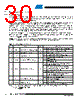
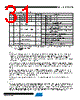
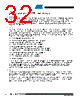
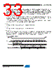
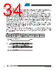
30 / 52 page  30 3686D–DFLASH–12/09 Atmel AT25DF321A 11. Status Register Commands 11.1 Read Status Register The two-byte Status Register can be read to determine the device’s ready/busy status, as well as the status of many other functions such as Hardware Locking and Software Protection. The Status Register can be read at any time, including during an internally self-timed program or erase operation. To read the Status Register, the CS pin must first be asserted and the opcode of 05h must be clocked into the device. After the opcode has been clocked in, the device will begin outputting Status Register data on the SO pin during every subsequent clock cycle. After the second byte of the Status Register has been clocked out, the sequence will repeat itself starting again with the first byte of the Status Register as long as the CS pin remains asserted and the clock pin is being pulsed. The data in the Status Register is constantly being updated, so each repeating sequence will output new data. The RDY/BSY status is available for both bytes of the Status Register and is updated for each byte. At clock frequencies above f CLK, the first two bytes of data output from the Status Register will not be valid. Therefore, if operating at clock frequencies above f CLK, at least four bytes of data must be clocked out from the device in order to read the correct values of both bytes of the Status Register. Deasserting the CS pin will terminate the Read Status Register operation and put the SO pin into a high-impedance state. The CS pin can be deasserted at any time and does not require that a full byte of data be read. Notes: 1. Only bit 7 of Status Register Byte 1 will be modified when using the Write Status Register Byte 1 command 2. R/W = Readable and writeable R = Readable only Table 11-1. Status Register Format – Byte 1 Bit (1) Name Type (2) Description 7 SPRL Sector Protection Registers Locked R/W 0 Sector Protection Registers are unlocked (default) 1 Sector Protection Registers are locked 6 RES Reserved for future use R 0 Reserved for future use 5 EPE Erase/Program Error R 0 Erase or program operation was successful 1 Erase or program error detected 4 WPP Write Protect (WP) Pin Status R 0 WP is asserted 1 WP is deasserted 3:2 SWP Software Protection Status R 00 All sectors are software unprotected (all Sector Protection Registers are 0) 01 Some sectors are software protected. Read individual Sector Protection Registers to determine which sectors are protected 10 Reserved for future use 11 All sectors are software protected (all Sector Protection Registers are 1 – default) 1 WEL Write Enable Latch Status R 0 Device is not write enabled (default) 1 Device is write enabled 0 RDY/BSY Ready/Busy Status R 0 Device is ready 1 Device is busy with an internal operation |
|
Link URL |
| War ALLDATASHEET hilfreich? [ DONATE ] |
Über Alldatasheet | Werbung | Kontakt | Privatsphäre und Datenschutz | Link zum Datenblatt | Linktausch | Hersteller All Rights Reserved©Alldatasheet.com |
| Russian : Alldatasheetru.com | Korean : Alldatasheet.co.kr | Spanish : Alldatasheet.es | French : Alldatasheet.fr | Italian : Alldatasheetit.com Portuguese : Alldatasheetpt.com | Polish : Alldatasheet.pl | Vietnamese : Alldatasheet.vn Indian : Alldatasheet.in | Mexican : Alldatasheet.com.mx | British : Alldatasheet.co.uk | New Zealand : Alldatasheet.co.nz |
|
Family Site : ic2ic.com |
icmetro.com |
 German ▼
 English
 Chinese
 German
 Japanese
 Russian
 Korean
 Spanish
 French
 Italian
 Portuguese
 Polish
 Vietnamese
 Indian
 Mexican
 British
 New Zealand