|
Datenblatt-Suchmaschine für elektronische Bauteile |
|
|
Datenblatt-Suchmaschine für elektronische Bauteile |
|
E39-R1 Datenblatt(PDF) 21 Page - Omron Electronics LLC |
|
|
|||||||||||||||||||||||||||||
E39-R1 Datenblatt(HTML) 21 Page - Omron Electronics LLC |
|
|
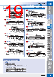
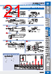
21 / 100 page  Beam Improvements Small-Spot, Reflective (Minute Object Detection) Beam Improvements Small-Spot, Reflective (Minute Object Detection) 20 20 Threaded Cylindrical Flat Sleeved Small Spot High Power Retro- reflective Limited- reflective Narrow view BGS Chemical- resistant, Oil-resistant Bending Heat- resistant Area Detection Liquid-level Vacuum FPD, Semi, Solar Installation Information 21 21 Installation Information Threaded Cylindrical Flat Sleeved Small Spot High Power Retro- reflective Limited- reflective Narrow view BGS Chemical- resistant, Oil-resistant Bending Heat- resistant Area Detection Liquid-level Vacuum FPD, Semi, Solar Small-spot Lens Unit → 22 Page Variable-spot, Parallel-light-spot, Integrated lens → This Page 5.6 Emitter Receiver Two, 2.2 dia. Sensing surface ( 10×24.5) Optic axis 11.5±0.1 Two, M3 Two, 3.2 dia., mounting holes Model display tube 10.9 29 14 11.5 6.9 13.6 25.6 11.6 Sensing head (Polyarylate) Sensing surface Two, 9 dia. lenses. Mounting hole dimensions Dimensions E32-C42 1M (No Cutting) + E39-F3A E39-F3A 21-A E32-C42 1M (No Cutting) + E39-F17 E39-F17 21-B E32-C31 2M (Free Cutting) + E39-F3C E39-F3C 21-C E32-C21N 2M (Free Cutting) + E39-F3C 21-D E32-C42S 1M (No Cutting) 21-E E32-L15 2M (Free Cutting) 21-F Reflective Fiber Units Installation Information → 58, 59 and 61 Page * Attached with adhesive and cannot be removed. Note: There is a white tube on the emitter fiber. 1,000 0 to 9 23 13 6 dia. 2 dia. (SUS303) 2.6 dia. Two, 1.2 dia. Fiber Attachment* Note: This is the Lens Unit for the E32-C42. Material: Aluminum for body and optical glass for lens. 23 13 3 M2×2 Allen-head set screw (for securing the fiber) 2.1 dia. 6 dia. 4 dia. Lens surface (lens diameter: 3.7 dia.) * Attached with adhesive and cannot be removed. Note: There is a white tube on the emitter fiber. 1,000 22.2 14 9.5 to 14 2.6 dia. Two, 1.2 dia. 6 dia. Fiber Attachment* 2 dia. (SUS303) Material: Aluminum for body and optical glass for lens. 6 dia. 5 dia. Lens surface (lens diameter: 5.4 dia.) 22.2 7.3 14 Note: There is a white line on the emitter fiber. 32.5 10.9 5.8 M3×0.5 (SUS303) Two, 1 dia. 27.5 5 dia. 2,000 E39-F9: Provided Note: There is a white line on the emitter fiber. Material: Aluminum for body and optical glass for lens. Note: This is the Lens Unit for the E32-C31 and E32-C31N. Lens surface (lens diameter: 3.7 dia.) M3×0.5 Effective screw length: 3 10.9 5.8 4.3 dia. 5 dia. Straight knurling * Attached with adhesive and cannot be removed. Note: There is a white tube on the emitter fiber. Sensing surface Lens: 2.4 dia. Two, 1.2 dia. 1.5 dia. Brancher (ABS resin): 3.5 dia. White marks: Emitter side (heat-shrinkable tube) 3 dia. (Aluminum) 1,000 15 (100) 18 Fiber Attachment* Note: There is a white tube on the emitter fiber. E39-F3A + E32-C42 16 14 Withdrew length I (mm) 12 10 8 6 4 2 0 4 8 12 16 20 0.08 0.22 : Spot diameter (mm) 0.17 0.10 0.13 l d Fiber I: Withdrew length d: Focal distance Spot: Small Focal distance: Short Withdrew length: Long Withdrew length: Short Spot: Large Focal distance: Long 0 5 10 15 20 25 30 35 40 0 2 4 6 8 1.6 0.9 0.6 0.3 Withdrew length I (mm) * Withdrew length: Approx. 1.3 to 5.8 mm E39-F17 + E32-C42 Spot: Small Focal distance: Short Withdrew length: Long Withdrew length: Short Spot: Large Focal distance: Long : Spot diameter (mm) l d Fiber I: Withdrew length d: Focal distance • Small-spot is ideal for detecting minute objects. Select the Fiber Unit that is best suited for the workpiece size and installation distance. (Refer to Reference Information for Model Selection) • Available with a variable-spot Lens Unit to change the spot diameter without replacing the fiber. The spot diameter can be adjusted according to the size of the workpiece by changing the withdrew length and sensing distance. Refer to the following graph, which shows the relation between the withdrew length, focal distance, and spot diameter. M3×0.5 (Trivalent chrome-plated zinc alloy) Two, 1.3 dia. 2,000 5 dia. Fiber Attachment (E39-F9W13) provided 20 6 10.9 5.8 E32-C42 1M Variable spot 0.1 to 0.6 dia. 6 to 15 0.3 to 1.6 dia. 10 to 30 R25 E39-F3A E39-F17 21-A 21-B Spot diameter Center distance (mm) Type Models Model Appearance (mm) Fiber Unit Lens Units + Fiber Units Lens Units Bending radius of cable 21 Page Dimensions No. Variable-spot types Lens Units + Fiber Unit E32-C31 2M Parallel light 4 dia. 0 to 20 R25 Flexible, R2 E32-C21N 2M E39-F3C 21-C 21-D Spot diameter Center distance (mm) Type Model Models Appearance (mm) Fiber Unit Lens Units + Fiber Units Lens Units Bending radius of cable 21 Page Dimensions No. Parallel-light-spot types Lens Units + Fiber Unit E32-C42S 1M Short-distance, Small-spot Long-distance, Small-spot 0.1 dia. 5 6 dia. 50 R25 E32-L15 2M 21-E 21-F Spot diameter Center distance (mm) Appearance (mm) Type Models Bending radius of cable 21 Page Dimensions No. Small-spot types Integrated Lens 6 dia. 2 dia. 23 6 dia. 2 dia. 22.2 M3 5 dia. 10.9 Lens: unnecessary 3 dia. 18 11.6 25.6 29 Lens: unnecessary IP50 IP50 * The spot diameter and the center distance are the same when using with E3X-HD series or E3NX-FA series. M3 5 dia. 10.9 Specifications - Reference Information for Model Selection - Reflective Fiber Units Spot diameter Center distance Optical axis diameter Models 0.1 dia. 5 2.4 0.1 dia. 7 3.7 0.2 dia. 17 4.8 0.5 dia. 7 3.7 0.5 dia. 17 4.8 4 dia. 0 to 20 3.7 6 dia. 50 10 3 dia. 50 9.4 Model Selection Tips <Map of Spot Diameters and Center Distances> (Unit: mm) E32-L15 E39-F3C + E32-C31 E32-C21N E39-F3B + E32-C31 E32-C21N E39-F3A-5 + E32-C31 E32-C21N E39-F3B + E32-C41 E39-F3A-5 + E32-C41 E32-C42S E39-F18 + E32-CC200 E32-C91N Center distance Spot diameter Optical axis diameter * * * * * Refer to page 22 for details. * Select the best model by following these steps. 1. Select the model based on the spot diameter suitable for the workpiece size. * The Variable-spot Type is useful if there are different sensing object sizes. 2. Select the model based on the allowable installation distance and center distance. |
|
Link URL |
| War ALLDATASHEET hilfreich? [ DONATE ] |
Über Alldatasheet | Werbung | Kontakt | Privatsphäre und Datenschutz | Link zum Datenblatt | Linktausch | Hersteller All Rights Reserved©Alldatasheet.com |
| Russian : Alldatasheetru.com | Korean : Alldatasheet.co.kr | Spanish : Alldatasheet.es | French : Alldatasheet.fr | Italian : Alldatasheetit.com Portuguese : Alldatasheetpt.com | Polish : Alldatasheet.pl | Vietnamese : Alldatasheet.vn Indian : Alldatasheet.in | Mexican : Alldatasheet.com.mx | British : Alldatasheet.co.uk | New Zealand : Alldatasheet.co.nz |
|
Family Site : ic2ic.com |
icmetro.com |
 German ▼
 English
 Chinese
 German
 Japanese
 Russian
 Korean
 Spanish
 French
 Italian
 Portuguese
 Polish
 Vietnamese
 Indian
 Mexican
 British
 New Zealand