|
Datenblatt-Suchmaschine für elektronische Bauteile |
|
|
Datenblatt-Suchmaschine für elektronische Bauteile |
|
E39-R Datenblatt(PDF) 56 Page - Omron Electronics LLC |
|
|
|||||||||||||||||||||||||||||
E39-R Datenblatt(HTML) 56 Page - Omron Electronics LLC |
|
|
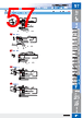
56 / 100 page  Special Applications Special Applications 56 56 Threaded Cylindrical Flat Sleeved Small Spot High Power Retro- reflective Limited- reflective Narrow view BGS Chemical- resistant, Oil-resistant Bending Heat- resistant Area Detection Liquid-level Vacuum FPD, Semi, Solar Installation Information 57 57 Installation Information Threaded Cylindrical Flat Sleeved Small Spot High Power Retro- reflective Limited- reflective Narrow view BGS Chemical- resistant, Oil-resistant Bending Heat- resistant Area Detection Liquid-level Vacuum FPD, Semi, Solar FPD, Semiconductors, and Solar Cells FPD, Semiconductors, and Solar Cells Limited-reflective → 54 page Through-beam → This page E32-T24SR 2M (Free Cutting) E32-A03-1 2M (Free Cutting) 57-D 57-B E32-T24S 2M (Free Cutting) E32-A04 2M (Free Cutting) 57-E E32-A03 2M (Free Cutting) 57-A 57-C 3.2 10 E39-L83 Mounting Bracket (SUS) (provided) 2.2 dia. 1.8 20.5 2 1.5 Sensing surface: 1.7 dia. 2,000 11 3.4 3.5 dia. 0.4 17.6 3.2 (SUS303) Note: Use the engraved surface and its opposing surface as installation (reference) surfaces. Note: Use the engraved surface and its opposing surface as installation (reference) surfaces. 2.95 dia. E39-L83 Mounting Bracket (SUS) (provided) 2 6 Sensing surface: 1.7 dia. E39-F9: Provided (SUS303) Engraved mark: 1 dia. 2,000 0.4 1.8 3.2 10 11 17.6 3.2 3.4 4.3 3.5 dia. 20.5 Note1: Use the engraved surface and its opposing surface as installation (reference) surfaces. 2. Set of two symmetrical parts. 13 12.5 3 6.5 2,000 Mounting holes Two, 3.4 dia Engraved mark: 1 dia. 1 dia. Sensing surface: 1.7 dia. (SUS303) 2.95 dia. 4.5 3.5 10 3 E39-F9: Provided 24.5 2 4 2,000 20.5 2 2 Sensing surface: 1.2 dia. 2 dia. E39-F9: Provided (SUS303) 1 dia. Engraved mark: 1 dia. 3.2 10 2.2 dia. 1.8 20.5 2 1.5 Sensing surface: 1.7 dia. 2,000 11 3.4 3.5 dia. 0.4 17.6 3.2 (SUS303) E39-L83 Mounting Bracket (SUS) (provided) 1,920 670 2,610 4,000 * 2,190 4,000 * 4,000 * 1,800 3.5 dia. 20.5 20.5 24.5 10 20.5 Thickness: 3 mm Thickness: 3 mm Thickness: 2 mm E32-T24SR 2M Application Ambient temperature Aperture angle 70°C 4° 3.4° 1.5° Wafer Mapping R10 R10 Flexible, R1 Flexible, R1 2 dia. (0.1 dia./ 0.03 dia.) 2 dia. (0.1 dia./ 0.03 dia.) 1.2 dia. (0.1 dia./ 0.03 dia.) E32-T24S 2M 57-D E32-A03 2M 57-A E32-A03-1 2M 57-B E32-A04 2M 57-C 57-E Appearance (mm) Bending radius of cable Sensing distance (mm) Optical axis diameter (minimum sensing object) Models 57 Page Dimensions No. 3,300 580 ST : SHS: 3,900 700 ST : SHS: 2,670 500 ST : SHS: 1,020 200 ST : SHS: 1,280 450 1,740 4,000 * E3X-HD 1,460 4,000 * 2,200 580 ST : SHS: 2,600 700 ST : SHS: 3,220 1,200 1,780 500 ST : SHS: 680 200 ST : SHS: IP50 IP50 IP50 IP50 * The optical fiber is 2 m long on each side, so the sensing distance is 4,000 mm. E3NX-FA The following mode names and response times apply to the modes given in the Sensing distance column. [E3X-HD] GIGA: Giga-power mode (16 ms), HS: High-speed mode (250 μs), ST: Standard mode (1 ms), and SHS: Super-high-speed mode (NPN output: 50 μs, PNP output: 55 μs) [E3NX-FA] GIGA: Giga-power mode (16 ms), HS: High-speed mode (250 μs), ST: Standard mode (1 ms), and SHS: Super-high-speed mode (30 μs) The values for the minimum sensing object are reference values that indicate values obtained in standard mode with the sensing distance and sensitivity set to the optimum values. The first value is for the E3X-HD and the second value is for the E3NX-FA. Note 1. 2. Other modes HS GIGA Other modes HS GIGA Wafer Mapping Specifications Dimensions • Wafer Mapping Through-beam Fiber Units Through-beam Fiber Units (Set of 2) Installation Information → 58, 60 Page 2 wafers 12-inch silicon wafer 150 mm 10 mm (E32-A04, High-speed mode) E32-A04+E3NX-FA21 Mapping Characteristics Digital value −10 0 2500 5000 7500 9999 −5 0 5 10 Thin-profile design enables easy mounting on robot arms. Reliably wafer detection, even when stacked closely together. Easy to adjust optical axis. (Typical alignment error between mechanical and optical axes is only ±0.1°.) Detection Detection |
|
Link URL |
| War ALLDATASHEET hilfreich? [ DONATE ] |
Über Alldatasheet | Werbung | Kontakt | Privatsphäre und Datenschutz | Link zum Datenblatt | Linktausch | Hersteller All Rights Reserved©Alldatasheet.com |
| Russian : Alldatasheetru.com | Korean : Alldatasheet.co.kr | Spanish : Alldatasheet.es | French : Alldatasheet.fr | Italian : Alldatasheetit.com Portuguese : Alldatasheetpt.com | Polish : Alldatasheet.pl | Vietnamese : Alldatasheet.vn Indian : Alldatasheet.in | Mexican : Alldatasheet.com.mx | British : Alldatasheet.co.uk | New Zealand : Alldatasheet.co.nz |
|
Family Site : ic2ic.com |
icmetro.com |
 German ▼
 English
 Chinese
 German
 Japanese
 Russian
 Korean
 Spanish
 French
 Italian
 Portuguese
 Polish
 Vietnamese
 Indian
 Mexican
 British
 New Zealand