|
Datenblatt-Suchmaschine für elektronische Bauteile |
|
|
Datenblatt-Suchmaschine für elektronische Bauteile |
|
E39-R Datenblatt(PDF) 73 Page - Omron Electronics LLC |
|
|
|||||||||||||||||||||||||||||
E39-R Datenblatt(HTML) 73 Page - Omron Electronics LLC |
|
|
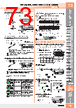
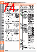
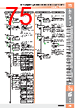
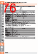
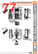
73 / 100 page  Fiber Amplifiers, Communications Unit and Accessories E3NX-FA Fiber Amplifiers, Communications Unit and Accessories E3NX-FA 72 Threaded Cylindrical Flat Sleeved Small Spot High Power Retro- reflective Limited- reflective Narrow view BGS Chemical- resistant, Oil-resistant Bending Heat- resistant Area Detection Liquid-level Vacuum FPD, Semi, Solar Installation Information 73 Installation Information Threaded Cylindrical Flat Sleeved Small Spot High Power Retro- reflective Limited- reflective Narrow view BGS Chemical- resistant, Oil-resistant Bending Heat- resistant Area Detection Liquid-level Vacuum FPD, Semi, Solar 72 73 Incident light level setting: The Step 3 incident level is adjusted to half the power tuning level. Threshold setting: Set to the same value as the Step 3 incident level. (4) Determine Workpiece Position • Position Tuning Press button without a workpiece in the area. 2. Place the workpiece at the desired position and hold button. 3. The green digital display changes [2pnt]→[p,s]. • Percentage Tuning • Smart Tuning Error Incident light level setting: The Step 2 incident light level is adjusted to the power tuning level. Threshold setting: Set to the value obtained by [Incident Level at Step 2 × (1 + Percentage Tuning Level)]. (5) Detect Transparent or Small Workpiece (Set Threshold by incident light level percentage) 1. Turn ON Percentage Tuning in SET mode. Error / Display / Cause Remedy Error Origin Tuning Type 2-point Tuning Full Auto Tuning All Tuning other than Maximum Sensitivity Tuning • Change the detection function mode to a slower response time mode. • Reduce the distance between the emitter and receiver. (Through-beam) • Place the Fiber Head closer to the sensing object. (Reflective) • Use a thin-diameter fiber. • Widen the emitter and receiver distance. (Through-beam) • Distance the Fiber Head from the sensing object. (Reflective) • Reduce the distance between the emitter and receiver. (Through-beam) • Place the Fiber Head closer to the sensing object. (Reflective) The light level difference between Points 1 and 2 are extremely small. Incident light level is too high. Incident light level is too low. Near Error Over Error Low Error No Smart Tuning other than Power Tuning can be used if Percentage Tuning is set. Refer to " Detailed Settings " to change the power tuning level. Turn ON power tuning in SET mode. Press button without a workpiece in the area. 2. Nomenclature 9999 p,5 1500 per Operating Procedures (1) Detect for Workpiece Presence/Absence (2) Enhance Durability of the Fiber Head against Dust and Dirt • 2-point Tuning 1. Press button with a workpiece in the detection area. 1. • Maximum Sensitivity Tuning Hold button for 3 seconds or longer with/without workpiece as shown below. Release the button when [ full] is displayed. Incident light level setting: The incident level in Step 1 is adjusted to "0". Threshold setting: The value is set to approx. 7% of the incident light level of 1. Incident light level setting: Adjust the max. incident light level on Step 1 as the power tuning level. Threshold setting: Set to the middle between max. and min. incident light levels on Step 1. 1. (3) Adjust for Moving Workpiece without Stopping Line • Full Auto Tuning Hold the button without the presence of a workpiece, and pass the workpiece through while [1pnt]→[ full]→[aut,] is displayed in green digital. (Keep holding the button while the workpiece passes through, and hold 7 seconds or longer until [aut,] is displayed in green digital. After the workpiece passes through, release your finger from the button.) 1. Press button again without a workpiece in the detection area. Release the button when [2pnt] is displayed. Incident light level setting: The larger incident level of the Step 1 and 2 values is adjusted to the power tuning level. Threshold setting: Set to the middle between the Step 1 and 2 incident light levels. 2. Through-beam: Workpiece is present Reflective: Workpiece is absent The green digital display changes [1pnt]→[full] Release the button when [ full] is displayed. Workpiece Workpiece Basic Settings Workpiece Setting is Completed Setting is Completed Setting is Completed Step 1 and Step 2 can be reversed. Hold for 3 seconds or longer Output switching Smart Tuning [Easy Sensitivity Setting] However, the Sensor becomes more susceptible to the influence of background objects. 1500 0 full 2500 2pnt aut, (6) Restore from the Incident Level Changed due to Dust and Dirt • Power Tuning Hold and buttons for 1 second or longer without a workpiece in the area. 1. Incident light level setting: The Step 1 incident level is adjusted to the power tuning level. Threshold setting: Not changed. Perform the procedure with a workpiece in the area for reflective model setting. If the setting is made after position tuning, set both the through-beam model and reflective model with a workpiece. Refer to " • Smart Tuning Error " for error displays. 1500 ptun l\c l\c [L/D Indicator] Indicates the setting status: Light-ON (L) or Dark-ON (D). [DPC Indicator] Turns ON when Dynamic Power Control is effective. [ L/D Button] Use to switch between Light-ON (L) and Dark-ON (D). [ L/D Button] Use to switch between Light-ON (L) and Dark-ON (D). [OUT Indicator] Turns ON when the output is ON. [ST Indicator] Turns ON when Smart Tuning is in progress. Threshold Level Green digital display Threshold Level Green digital display Incident Level White digital display Incident Level White digital display [+–UP/DOWN Button] Used to fine-tune the threshold or change set values. [ MODE Button] Use to switch between Detection Mode and Setting Mode. [ MODE Button] Use to switch between Detection Mode and Setting Mode, and use to switch between OUT1 and OUT2. Executes Smart Tuning. [ TUNE Button] Executes Smart Tuning. [ TUNE Button] [L/D Indicator] Indicates the setting status: Light-ON (L) or Dark-ON (D). [DPC Indicator] Turns ON when Dynamic Power Control is effective. [OUT1 Indicator/OUT2 Indicator] Turns ON when OUT1 or OUT2 is ON. [OUT1 Selection Indicator/OUT2 Selection Indicator] The indicator for the selected output channel is lit. [ST Indicator] Turns ON when Smart Tuning is in progress. [+–UP/DOWN Button] Used to fine-tune the threshold or change set values. E3NX-FA11/FA41/FA6/FA8/FA7/FA9/FA24/FA54 E3NX-FA21/FA51/FA7TW/FA9TW/FA54TW/FA0 Basic Settings TUNE TUNE Refer to “Detailed Settings” Refer to “Detailed Settings” Hold for 3 seconds or longer Setting is Completed Setting is Completed Setting is Completed (2) Reset Settings • Setting Reset Hold button and then hold button for 3 seconds or longer. 1. 2. (1) Stable Detection Regardless of Incident Level Change due to Dust and Dirt • DPC Function (Use of the function with Through-beam model or Retro-reflective model is recommended) Perform Smart Tuning. 1. Set the DPC function ON in SET mode. 2. Initializes all the settings by returning them to the factory defaults. Minute Adjustment of Threshold Level Press button to adjust the threshold level. 1. Hold the key for high-speed level adjustment. The threshold level becomes higher. The threshold level becomes lower. Channel switching Models with 2 Outputs: E3NX-FA21,E3NX-FA51,E3NX-FA7TW, E3NX-FA9TW and E3NX-FA54TW The OUT selection indicators and the settings will change. Press button for 1 second. The OUT selection indicators (OUT1/OUT2) switch. 1. 2. OUT selection indicator (OUT1) [Output 1] OUT selection indicator (OUT2) Press the MODE button for 1 second in detection mode. [Output 2] In the detailed settings, the OUT selection indicators will each light whenever the output (OUT1/OUT2) is set. (3) Save or Read Settings 1. Refer to "Smart Tuning" Refer to "Power Tuning" Refer to “Detailed Settings” . Incident Light Level Threshold Level Stabilizes the displayed incident level by correcting internal incident level changes. Time Displayed incident Light Level The displayed incident level decreases and the DPC indicator starts blinking when incident level correction is not possible. rst Hold both for 3 sec. or longer The DPC indicator turns ON when the DPC function is effective. Convenient Setting Features (4) Prevent Mistake-operation • Key Lock Function Hold both for 3 sec. or longer * Press either of UP/DOWN. 3. Internal Incident Light Level MODE UP/DOWN MODE UP/DOWN Select [rst ] in and press button. Select [rst] in and press button. Hold button and then hold button for 3 seconds or longer. L/D TUNE Saves the current settings. Reads out the saved settings. Select [save] in and press button. 2. UP/DOWN MODE Select [rst] in and press button. 2. UP/DOWN MODE Select [save yes] in and press button. 3. UP/DOWN MODE Select [rst user] in and press button. 3. UP/DOWN MODE • User Save Function • User Reset Function Disables all button operations. [ ] is displayed when the button is pressed. Enable/Cancel (This procedure) Hold both for 1 sec. or longer Hold for 1 sec. or longer Workpiecet Hold for 7 seconds or longer 9999 1pnt 9999 1pnt 1. Press button. Through-beam: Set to “Dark ON" to turn the output ON with a workpiece in the detection area. [L/D Indicator] turns ON. Reflective: Set to “Light ON" to turn the output ON with a workpiece in the detection area. [L/D Indicator] turns ON. L/D D L |
|
Link URL |
| War ALLDATASHEET hilfreich? [ DONATE ] |
Über Alldatasheet | Werbung | Kontakt | Privatsphäre und Datenschutz | Link zum Datenblatt | Linktausch | Hersteller All Rights Reserved©Alldatasheet.com |
| Russian : Alldatasheetru.com | Korean : Alldatasheet.co.kr | Spanish : Alldatasheet.es | French : Alldatasheet.fr | Italian : Alldatasheetit.com Portuguese : Alldatasheetpt.com | Polish : Alldatasheet.pl | Vietnamese : Alldatasheet.vn Indian : Alldatasheet.in | Mexican : Alldatasheet.com.mx | British : Alldatasheet.co.uk | New Zealand : Alldatasheet.co.nz |
|
Family Site : ic2ic.com |
icmetro.com |
 German ▼
 English
 Chinese
 German
 Japanese
 Russian
 Korean
 Spanish
 French
 Italian
 Portuguese
 Polish
 Vietnamese
 Indian
 Mexican
 British
 New Zealand