|
Datenblatt-Suchmaschine für elektronische Bauteile |
|
|
Datenblatt-Suchmaschine für elektronische Bauteile |
|
UPD161623 Datenblatt(PDF) 8 Page - NEC |
|
|
|||||||||||||||||||||||||||||
UPD161623 Datenblatt(HTML) 8 Page - NEC |
|
|
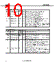
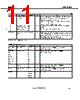
8 / 83 page  Data Sheet S15817EJ2V0DS 8 µµµµPD161623 3. PIN FUNCTIONS 3.1 Power Supply System Pins Symbol Pin Name Pad No. I/O Function VDD1 Logic power supply 77, 95 − Power supply pin for logic circuit VDD2 I/O power supply 96, 108, 109 − Power supply pin for I/O buffer VS Driver power supply 103, 104 − Power supply pin for driver circuit VSS Ground 94, 97, 98, 105 − Ground pin for logic and driver circuits V0 to V5 VRH VRL1, VRL2 Power supply for γ-curve correction 120 to 125, 119, 126, 127 − The µ PD161623 includes power supplies and registers for the γ-curve, so if the characteristics of the γ-curve and LCD panel in the µ PD161623 match, leave V0 to V5, VRH, VRL1, VRL2 open. If some kind of correction is required, adjust the γ-curve by connecting registers between the V0 to V5, VRH, VRL1, VRL2 pins (see 5.9 γγγγ-Curve Correction Power Supply Circuit). VDD1 (MODE) Mode setting pull-up power supply 81, 85 − Pull-up power supply pin for mode setting VDD2 (MODE) Mode setting pull-down power supply 42, 116 − Pull-down power supply pin for mode setting VSS (MODE) Mode setting ground 35, 44, 46, 48, 68, 74, 79, 83, 113, 118, 128, 140 − Ground pin for mode setting 3.2 Logic System Pins (1/2) Symbol Pin Name Pad No. I/O Function This pin is used to select the CPU interface mode. PSX0 CPU Interface Mode H 18-bit parallel interface L 16-bit parallel interface PSX0 CPU interface selection 80 Input /CS Chip select 69 Input This pin is used for chip select signals. When /CS = L, the chip is active and can perform data input/output operations including command and data I/O. /RESET Reset 70 Input When /RESET is L, an internal reset is performed. The reset operation is executed at the /RESET signal level. Be sure to perform reset via this pin at power application. /RD (E) Read (Enable) 73 Input When i80 series parallel data transfer (/RD) has been selected, the signal at this pin is used to enable read operations. Data is output to the data bus only when this pin is low. When M68 series parallel data transfer (E) has been selected, the signal at this pin is used to enable read/write operations. /WR (R, /W) Write (Read/write) 72 Input When i80 series parallel data transfer (/WR) has been selected, the signal at this pin is used to enable write operations. Data is written at the rising edge of this signal. When M68 series parallel data transfer (R, /W) and serial data has been selected, this pin is used to determine the direction of data transfer. L: Write H: Read C86 Select interface 82 Input This pin is used to switch between interface modes (i80 series CPU or M68 series CPU). L: Selects i80 series CPU mode H: Selects M68 series CPU mode |
|
Link URL |
| War ALLDATASHEET hilfreich? [ DONATE ] |
Über Alldatasheet | Werbung | Kontakt | Privatsphäre und Datenschutz | Link zum Datenblatt | Linktausch | Hersteller All Rights Reserved©Alldatasheet.com |
| Russian : Alldatasheetru.com | Korean : Alldatasheet.co.kr | Spanish : Alldatasheet.es | French : Alldatasheet.fr | Italian : Alldatasheetit.com Portuguese : Alldatasheetpt.com | Polish : Alldatasheet.pl | Vietnamese : Alldatasheet.vn Indian : Alldatasheet.in | Mexican : Alldatasheet.com.mx | British : Alldatasheet.co.uk | New Zealand : Alldatasheet.co.nz |
|
Family Site : ic2ic.com |
icmetro.com |
 German ▼
 English
 Chinese
 German
 Japanese
 Russian
 Korean
 Spanish
 French
 Italian
 Portuguese
 Polish
 Vietnamese
 Indian
 Mexican
 British
 New Zealand