|
Datenblatt-Suchmaschine für elektronische Bauteile |
|
|
Datenblatt-Suchmaschine für elektronische Bauteile |
|
AT25QL128A Datenblatt(PDF) 14 Page - Dialog Semiconductor |
|
|
|||||||||||||||||||||||||||||
AT25QL128A Datenblatt(HTML) 14 Page - Dialog Semiconductor |
|
|
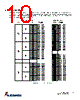
14 / 84 page  13 AT25QL128A DS-AT25QL128A–129E–01-2021 factory default setting for the block protection bits is 0, none of the array protected. 7.4 Top/Bottom Block Protect (TB) The Top/Bottom bit (TB) is a non-volatile bit in the status register (S5) that specifies if the Block Protect Bits (BP2, BP1, BP0) protect from the top (TB = 0) or the bottom (TB = 1) of the array, as shown in Table 7-2 and Table 7-3. The factory default setting is TB = 0. The TB bit can be set with the Write Status Register Instruction, depending on the state of the SRP0, SRP1 and WEL bits. 7.5 Sector/Block Protect (SEC) The Sector protect bit (SEC) is a non-volatile bit in the status register (S6) that specifies if the Block Protect Bits (BP2, BP1, BP0) protect a 4-kbyte sector (SEC = 1) or 64-kbyte blocks (SEC = 0) in the top (TB = 0) or the bottom (TB = 1) of the array, as shown in Table 7-2 and Table 7-3. The default setting is SEC = 0. 7.6 Status Register Protect (SRP1, SRP0) The Status Register Protect bits (SRP1 and SRP0) are non-volatile read/write bits in the status register (S8 and S7). The SRP bits control the method of write protection: software protection, hardware protection, power supply lock-down, or one-time programmable (OTP) protection. Note: 1. When SRP1, SRP0 = (1,0), a power down, power-up cycle changes SRP1, SRP0 to (0,0). 7.7 Quad Enable (QE) The Quad Enable (QE) bit is a non-volatile read/write bit in the Status Register (S9) that allows Quad operation. When the QE bit is set to 1 (factory default), the Quad IO2 and IO3 pins are enabled. 7.8 Complement Protect (CMP) The Complement Protect bit (CMP) is a non-volatile read/write bit in the status register (S14). It is used in conjunction with SEC, TB, BP2, BP1, and BP0 bits to provide more flexibility for the array protection. Once CMP is set to 1, previous array protection set by SEC, TB, BP2, BP1, and BP0 is reversed. For instance, when CMP = 0, a top 4-kbyte sector can be protected while the rest of the array is not; when CMP = 1, the top 4-kbyte sector becomes unprotected while the rest of the array becomes read-only. See Table 7-2 and Table 7-3 for details. The default setting is CMP = 0. Table 7-1. Encoding of SRP[1:0] Bits and Write Protection SRP1 SRP0 WP Status Register Description 0 0 X Software Protection WP pin no control. The register can be written to after a Write Enable instruction, WEL = 1. [Factory Default] 0 1 0 Hardware Protected When the WP pin is low, the Status Register is locked and can not be written to. 0 1 1 Hardware Unprotected When the WP pin is high, the Status register is unlocked and can be written to after a Write Enable instruction, WEL = 1. 1 0 X Power Supply Lock- Down Status Register is protected and cannot be written to again until the next power down, power-up cycle.(1) 1 1 X One Time Program Status Register is permanently protected and cannot be written to. |
|
Link URL |
| War ALLDATASHEET hilfreich? [ DONATE ] |
Über Alldatasheet | Werbung | Kontakt | Privatsphäre und Datenschutz | Link zum Datenblatt | Linktausch | Hersteller All Rights Reserved©Alldatasheet.com |
| Russian : Alldatasheetru.com | Korean : Alldatasheet.co.kr | Spanish : Alldatasheet.es | French : Alldatasheet.fr | Italian : Alldatasheetit.com Portuguese : Alldatasheetpt.com | Polish : Alldatasheet.pl | Vietnamese : Alldatasheet.vn Indian : Alldatasheet.in | Mexican : Alldatasheet.com.mx | British : Alldatasheet.co.uk | New Zealand : Alldatasheet.co.nz |
|
Family Site : ic2ic.com |
icmetro.com |
 German ▼
 English
 Chinese
 German
 Japanese
 Russian
 Korean
 Spanish
 French
 Italian
 Portuguese
 Polish
 Vietnamese
 Indian
 Mexican
 British
 New Zealand