|
Datenblatt-Suchmaschine für elektronische Bauteile |
|
|
Datenblatt-Suchmaschine für elektronische Bauteile |
|
CC1010-RTY1 Datenblatt(PDF) 16 Page - Texas Instruments |
|
|
|||||||||||||||||||||||||||||
CC1010-RTY1 Datenblatt(HTML) 16 Page - Texas Instruments |
|
|
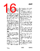
16 / 150 page  CC1010 SWRS047A Page 16 of 146 RBIAS Current output from internal band gap cell bias generator. A precision resistor (82 k Ω, ±1%) should be connected between this pin and ground to set the correct bias current level. XOSC_Q1, XOSC_Q2 These are the main oscillator connection pins. An external crystal should be connected between these pins, and load capacitors should be connected between each pin and ground. If an external oscillator is used, the clock signal should be connected to the XOSC_Q1 pin, and XOSC_Q2 should be left open (not connected). XOSC32_Q1, XOSC32_Q2 These are the real time clock (RTC) oscillator connection pins. An external crystal should be connected between these pins, and load capacitors should be connected between each pin and ground. If an external oscillator is used, the clock signal should be connected to the XOSC32_Q1 pin, and XOSC32_Q2 should be left open (not connected). POR_E Enable signal for the on-chip power-on reset module. The power-on reset is enabled when POR_E is connected to DVDD and disabled when connected to DGND . PROG Active low Flash programming enable pin. When this signal is active (driven to DGND) a Flash programmer can be connected to the SPI interface. Under normal operation it must be driven to DVDD. RESET Active low asynchronous system reset. It has an internal pull-up resistor and can be left unconnected during normal operation. AD0, AD1 Analog inputs to A/D converter channels 0 and 1 respectively. When not used these pins can be left open (not connected). AD2 (RSSI/IF) Analog input to A/D converter channel 2. This pin can also be configured to be RSSI output or IF output. The pin is configured by the FREND register. When not used this pin can be left open (not connected). PORT 0 Port 0 is a 4-bit (P0.3-P0.0) bi-directional CMOS I/O port with 2 mA drivers. A direction register (P0DIR) controls whether each pin is an output or input and the register P0 is used to read the input or control the logical value of the output. Pins P0.0 - P0.2 can be configured to become a master SPI interface in register SPCR and will then override P0(2:0), P0DIR(2) and P0DIR(1). Used as SPI interface, P0.0 is SCK, P0.1 is MOSI, and P0.2 is MISO. PORT 1 Port 1 is an 8-bit (P1.7-P1.0) bi- directional CMOS I/O port with 2 mA drivers. A direction register (P1DIR) controls whether each pin is an output or input and the register P1 is used to read the input or control the logical value of the output. PORT 2 Port 2 is an 8-bit (P2.7-P2.0) bi- directional CMOS I/O port with 2 mA drivers, except for P2.3 that has an 8 mA output buffer. A direction register (P2DIR) controls whether each pin is an output or input and the register P2 is used to read the input or control the logical value of the output. Pins P2.0 and P2.1 can be configured to become the RXD1 and TXD1 pin, respectively, of UART 1. Pin P2.2 has a Schmitt-trigger input stage. Note that while this pin does have hysteresis, it will draw a large input current (~0.5 mA) if the input voltage is close to VDD/2. PORT 3 Port 3 is a 6-bit (P3.5-P3.0) bi-directional CMOS I/O port with 2 mA drivers. A direction register (P3DIR) controls whether each pin is an output or input. The register P3 is used to read the input or control the logical value of the output. |
|
Link URL |
| War ALLDATASHEET hilfreich? [ DONATE ] |
Über Alldatasheet | Werbung | Kontakt | Privatsphäre und Datenschutz | Link zum Datenblatt | Linktausch | Hersteller All Rights Reserved©Alldatasheet.com |
| Russian : Alldatasheetru.com | Korean : Alldatasheet.co.kr | Spanish : Alldatasheet.es | French : Alldatasheet.fr | Italian : Alldatasheetit.com Portuguese : Alldatasheetpt.com | Polish : Alldatasheet.pl | Vietnamese : Alldatasheet.vn Indian : Alldatasheet.in | Mexican : Alldatasheet.com.mx | British : Alldatasheet.co.uk | New Zealand : Alldatasheet.co.nz |
|
Family Site : ic2ic.com |
icmetro.com |
 German ▼
 English
 Chinese
 German
 Japanese
 Russian
 Korean
 Spanish
 French
 Italian
 Portuguese
 Polish
 Vietnamese
 Indian
 Mexican
 British
 New Zealand