|
Datenblatt-Suchmaschine für elektronische Bauteile |
|
|
Datenblatt-Suchmaschine für elektronische Bauteile |
|
CC1010-RTY1 Datenblatt(PDF) 73 Page - Texas Instruments |
|
|
|||||||||||||||||||||||||||||
CC1010-RTY1 Datenblatt(HTML) 73 Page - Texas Instruments |
|
|
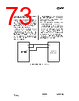
73 / 150 page  CC1010 SWRS047A Page 73 of 146 rate as set by SPCR.DORD, SPCR.CPOL, SPCR.CPHA and SPCR.SPR. Reading data from SPDR will read the input buffer, which is only updated after each complete transmission. This means that a new byte can be written to SPDR before reading the newly received byte in order to maximise the data rate. If data is written to SPDR while a transmission is in progress, this is regarded as a collision. After each new byte written to SPDR, the write collision flag SPSR.WCOL is updated. If a collision occurs, the data written to SPDR is ignored and the data must be written to SPDR again for it to be sent. It is also possible to check the SPI status bit, SPSR.SPA, before writing to SPDR to avoid collisions. This bit is set only when data is being transmitted. SPI timing, data order, clock polarity and clock phase are shown in Figure 18. It is also possible to use the master SPI interface to interface with a two-pin serial interface that uses a bi-directional data line (such as the interface used by the Chipcon CC1000 RF transceiver). In this case, you would connect the MO and MI pins together on your PCB, as shown in Figure 17. In the software, the P0DIR.1 bit must be set correctly according to whether data is being written or read. CC1010 Two-wire peripheral MO MI SCK DIO DCLK Figure 17. Two-wire serial interface |
|
Link URL |
| War ALLDATASHEET hilfreich? [ DONATE ] |
Über Alldatasheet | Werbung | Kontakt | Privatsphäre und Datenschutz | Link zum Datenblatt | Linktausch | Hersteller All Rights Reserved©Alldatasheet.com |
| Russian : Alldatasheetru.com | Korean : Alldatasheet.co.kr | Spanish : Alldatasheet.es | French : Alldatasheet.fr | Italian : Alldatasheetit.com Portuguese : Alldatasheetpt.com | Polish : Alldatasheet.pl | Vietnamese : Alldatasheet.vn Indian : Alldatasheet.in | Mexican : Alldatasheet.com.mx | British : Alldatasheet.co.uk | New Zealand : Alldatasheet.co.nz |
|
Family Site : ic2ic.com |
icmetro.com |
 German ▼
 English
 Chinese
 German
 Japanese
 Russian
 Korean
 Spanish
 French
 Italian
 Portuguese
 Polish
 Vietnamese
 Indian
 Mexican
 British
 New Zealand