|
Datenblatt-Suchmaschine für elektronische Bauteile |
|
|
Datenblatt-Suchmaschine für elektronische Bauteile |
|
CC1010-RTY1 Datenblatt(PDF) 85 Page - Texas Instruments |
|
|
|||||||||||||||||||||||||||||
CC1010-RTY1 Datenblatt(HTML) 85 Page - Texas Instruments |
|
|
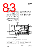
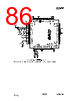
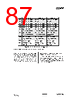
85 / 150 page  CC1010 SWRS047A Page 85 of 146 17.3 RF Application Circuit Very few external components are required for operation of the RF transceiver. A typical application circuit is shown in Figure 20. Component values are shown in Table 28. 17.3.1 Input / output matching C31/L32 is the input match for the receiver, and L32 is also used as a DC choke for biasing. C41, L41 and C42 are used to match the transmitter to a 50-Ohm load. An internal T/R switch circuit makes it possible to connect the input and output together and match the transceiver to 50 Ω in both RX and TX mode. See the Input / Output Matching section on page 126 for details. 17.3.2 VCO inductor The VCO is completely integrated except for the inductor L101. Component values for the matching network and VCO inductor are easily calculated using the SmartRF ® Studio software for any operation frequency. 17.3.3 Additional filtering Additional external components (e.g. RF LC or SAW-filter) may be used in order to improve the performance in specific applications. See also the Optional LC Filter section on page 128 for further information. If a SAW filter is used, it should be included in the RX path only (an external RX/TX switch should then be used). 17.3.4 Voltage supply decoupling Voltage supply filtering and de-coupling capacitors must be used (not shown in the application circuit). These capacitors should be placed as close as possible to the voltage supply pins of CC1010. The placement and size of the decoupling capacitors and power supply filtering are very important to achieve the best sensitivity and lowest possible LO leakage and the reference layouts should be followed. |
|
Link URL |
| War ALLDATASHEET hilfreich? [ DONATE ] |
Über Alldatasheet | Werbung | Kontakt | Privatsphäre und Datenschutz | Link zum Datenblatt | Linktausch | Hersteller All Rights Reserved©Alldatasheet.com |
| Russian : Alldatasheetru.com | Korean : Alldatasheet.co.kr | Spanish : Alldatasheet.es | French : Alldatasheet.fr | Italian : Alldatasheetit.com Portuguese : Alldatasheetpt.com | Polish : Alldatasheet.pl | Vietnamese : Alldatasheet.vn Indian : Alldatasheet.in | Mexican : Alldatasheet.com.mx | British : Alldatasheet.co.uk | New Zealand : Alldatasheet.co.nz |
|
Family Site : ic2ic.com |
icmetro.com |
 German ▼
 English
 Chinese
 German
 Japanese
 Russian
 Korean
 Spanish
 French
 Italian
 Portuguese
 Polish
 Vietnamese
 Indian
 Mexican
 British
 New Zealand