|
Datenblatt-Suchmaschine für elektronische Bauteile |
|
|
Datenblatt-Suchmaschine für elektronische Bauteile |
|
CC1010-RTY1 Datenblatt(PDF) 35 Page - Texas Instruments |
|
|
|
|||||||||||||||||||||||||||||
CC1010-RTY1 Datenblatt(HTML) 35 Page - Texas Instruments |
|
|
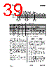
35 / 152 page  CC1010 SWRS047 Page 35 of 152 Mode Core Peripherals Typical current consumption 1 Exit condition Main osc. Main osc. 14.8 mA at 14.7456 MHz Writing SFR Active RTC osc. (32 kHz) RTC osc. (32 kHz) 1.3 mA Writing SFR Stopped Main osc. 12.8 mA at 14.7456 MHz Idle Stopped RTC osc. (32 kHz) ADC Off 29.4 uA Interrupt Reset Power off/on Stopped ADC On (32 kHz) 200 uA ADC value exceeds threshold Reset Power off/on Power-Down Stopped Stopped 0.2 uA Reset Power off/on Note 1: Flash duty-cycle reduction is used for all modes Table 15. Operating modes summary 15.9.4 Clock Modes The 8051 and its peripherals can be run on both the main crystal oscillator (Clock Mode 0) and the 32.768 kHz oscillator (Clock Mode 1). The clock mode is set in X32CON.CMODE. 15.9.5 Entering Clock Mode 1 from Clock Mode 0 After reset, the 8051 and its peripherals are running on the main crystal oscillator, and the 32.768 kHz oscillator is in power down. To enter Clock Mode 1, the 32.768 kHz oscillator must first be powered up. This requires clearing X32CON.X32_PD and then waiting at least 160 ms, after which X32CON.CMODE can be set to enter Clock Mode 1. If an external 32.768 kHz clock source is already available in the system, this clock can be applied to the XOSC32_Q1 pin after setting the X32CON.X32_BYPASS bit. After 2 to 3 clock periods on the 32.768 kHz oscillator, a glitch free transition has been made from the main crystal oscillator to the 32.768 kHz oscillator. If desired, the main crystal oscillator can then be set in power down to save more power by setting RFMAIN.CORE_PD and RFMAIN.BIAS_PD. This has the disadvantage that a later transition from Clock Mode 1 to Clock Mode 0 will require the main crystal oscillator to be powered up again. Since the Flash program memory draws a static current, Idle Mode together with Flash Power Control (see page 44) should be applied for maximum power saving in Clock Mode 1. The RF receiver cannot be activated in Clock Mode 1. 15.9.6 Entering Clock Mode 0 from Clock Mode 1 To enter Clock Mode 0 from Clock Mode 1, the main crystal oscillator must first be set in power up (if powered down). This requires clearing RFMAIN.CORE_PD and RFMAIN.BIAS_PD and then waiting at least 5 ms (depend on main oscillator frequency, see Electrical Specifications page 7). If the oscillator is already powered up, no waiting is required. Clearing X32CON.CMODE will then cause a glitch free transition from Clock Mode 1 to Clock Mode 0 after 2 to 3 clock periods on the main crystal oscillator. 15.9.7 Flash Power Control The Flash program memory current consumption can be controlled as described in the Flash Power Control section on page 44. |
|
Link URL |
| War ALLDATASHEET hilfreich? [ DONATE ] |
Über Alldatasheet | Werbung | Kontakt | Privatsphäre und Datenschutz | Link zum Datenblatt | Linktausch | Hersteller All Rights Reserved©Alldatasheet.com |
| Russian : Alldatasheetru.com | Korean : Alldatasheet.co.kr | Spanish : Alldatasheet.es | French : Alldatasheet.fr | Italian : Alldatasheetit.com Portuguese : Alldatasheetpt.com | Polish : Alldatasheet.pl | Vietnamese : Alldatasheet.vn Indian : Alldatasheet.in | Mexican : Alldatasheet.com.mx | British : Alldatasheet.co.uk | New Zealand : Alldatasheet.co.nz |
|
Family Site : ic2ic.com |
icmetro.com |
 German ▼
 English
 Chinese
 German
 Japanese
 Russian
 Korean
 Spanish
 French
 Italian
 Portuguese
 Polish
 Vietnamese
 Indian
 Mexican
 British
 New Zealand