|
Datenblatt-Suchmaschine für elektronische Bauteile |
|
|
Datenblatt-Suchmaschine für elektronische Bauteile |
|
CC1010-RTY1 Datenblatt(PDF) 67 Page - Texas Instruments |
|
|
|
|||||||||||||||||||||||||||||
CC1010-RTY1 Datenblatt(HTML) 67 Page - Texas Instruments |
|
|
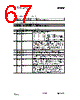
67 / 152 page  CC1010 SWRS047 Page 67 of 152 SBUF0 (0x99) - Serial Port 0, data buffer Bit Name R/W Reset value Description 7:0 SBUF0(7:0) R/W 0x00 Serial Port 0, data buffer. SBUF1 (0xC1) – Serial Port 1, data buffer Bit Name R/W Reset value Description 7:0 SBUF1(7:0) R/W 0x00 Serial Port 1, data buffer SCON0 (0x98) - Serial Port 0 Control Register Bit Name R/W Reset value Description 7 SM0_0 R/W 0 6 SM1_0 R/W 0 Serial Port 0 mode bits, decoded as: SM0_0 SM1_0 Mode 0 0 0 (Synchronous half duplex) 0 1 1 (Asynchronous full duplex, start + stop bit) 1 0 2 (Asynchronous full duplex, start + stop bit, 9th data bit) 1 1 3 (Asynchronous full duplex, start + stop bit, 9th data bit) 5 SM2_0 R/W 0 Multiprocessor communication enable. In modes 2 and 3 SM2_0 = 1 enables the multiprocessor communication feature: In mode 2 or 3 RI_0 will not be activated if the received 9th bit is 0. If SM2_0 = 1 in mode 1, RI_0 will only be activated if a valid stop bit is received. In mode 0 SM2_0 establishes the baud rate: when SM2_0 = 0 the baud rate is clk / 12; when SM2_0 = 1 the baud rate is clk / 4. 4 REN_0 R/W 0 Receive enable. When REN_0 = 1 reception is enabled. 3 TB8_0 R/W 0 Defines the state of the 9th data bit transmitted in modes 2 and 3. 2 RB8_0 R/W 0 In modes 2 and 3 RB8_0 indicates the state of the 9th bit received. In mode 1 RB8_0 indicates the state of the received stop bit. In mode 0 RB8_0 is not used. 1 TI_0 R/W 0 Transmit interrupt flag. Indicates that the transmit data word has been shifted out. In mode 0 TI_0 is set at the end of the 8th data bit. In all other modes TI_0 is set when the stop bit is placed on the TXD0 pin. TI_0 must be cleared by the software. 0 RI_0 R/W 0 Receive interrupt flag. Indicates that a serial data word has been received. In mode 0 RI_0 is set at the end of the 8th data bit. In mode 1 RI_0 is set after the last sample of the incoming stop bit, subject to the state of SM2_0. In modes 2 and 3 RI_0 is set at the end of the last sample of RB8_0. RI_0 must be cleared by the software. |
|
Link URL |
| War ALLDATASHEET hilfreich? [ DONATE ] |
Über Alldatasheet | Werbung | Kontakt | Privatsphäre und Datenschutz | Link zum Datenblatt | Linktausch | Hersteller All Rights Reserved©Alldatasheet.com |
| Russian : Alldatasheetru.com | Korean : Alldatasheet.co.kr | Spanish : Alldatasheet.es | French : Alldatasheet.fr | Italian : Alldatasheetit.com Portuguese : Alldatasheetpt.com | Polish : Alldatasheet.pl | Vietnamese : Alldatasheet.vn Indian : Alldatasheet.in | Mexican : Alldatasheet.com.mx | British : Alldatasheet.co.uk | New Zealand : Alldatasheet.co.nz |
|
Family Site : ic2ic.com |
icmetro.com |
 German ▼
 English
 Chinese
 German
 Japanese
 Russian
 Korean
 Spanish
 French
 Italian
 Portuguese
 Polish
 Vietnamese
 Indian
 Mexican
 British
 New Zealand