|
Datenblatt-Suchmaschine für elektronische Bauteile |
|
|
Datenblatt-Suchmaschine für elektronische Bauteile |
|
ADP1876ACPZ-R7 Datenblatt(PDF) 15 Page - Analog Devices |
|
|
|||||||||||||||||||||||||||||
ADP1876ACPZ-R7 Datenblatt(HTML) 15 Page - Analog Devices |
|
|
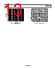
15 / 24 page  Data Sheet ADP1876 Rev. A | Page 15 of 24 The LDO has been optimized to handle these transients without overload faults. Due to the gate drive loading, using the VCCO output for other external auxiliary system loads is not recom- mended. The LDO includes a current limit well above the expected maximum gate drive load. This current limit also includes a short-circuit fold back to further limit the VCCO current in the event of a short-circuit fault. The VDL pin provides power to the low-side driver. Connect VDL to VCCO. Bypass VDL to PGND with a 1 µF (minimum) ceramic capacitor, which must be placed close to the VDL pin. For an input voltage of less than 5.5 V, it is recommended to bypass the LDO by connecting VIN to VCCO, as shown in Figure 25, thus eliminating the dropout voltage. However, for example, if the input range is 4 V to 7 V, the LDO cannot be bypassed by shorting VIN to VCCO because the 7 V input has exceeded the maximum voltage rating of the VCCO pin. In this case, use the LDO to drive the internal drivers noting that there is a dropout when VIN is less than 5 V. Figure 25. Configuration for VIN < 5.5 V OVERVOLTAGE PROTECTION The ADP1876 operates at a 600 kHz fixed frequency PWM. When the output is shorted to a voltage higher than the regu- lation voltage, the duty cycle of the controller modulates to keep the output stable at the preset regulation voltage by sinking current through the low-side N-channel MOSFET during the off cycle. POWER GOOD The PGOODx pin is an open-drain NMOS with an internal 12 kΩ pull-up resistor connected between PGOODx and VCCO. PGOODx is internally pulled up to VCCO during normal operation and is active low when tripped. When the feedback voltage, VFB, rises above the overvoltage threshold or drops below the undervoltage threshold, the PGOODx output is pulled to ground after a delay of 12 µs. The overvoltage or under- voltage condition must exist for more than 12 µs for PGOODx to become active. The PGOODx output also becomes active if a thermal overload condition is detected. SHORT-CIRCUIT AND CURRENT-LIMIT PROTECTION When the output is shorted or the output current exceeds the current limit set by the current-limit setting resistor (between ILIMx and SWx) for eight consecutive cycles, the ADP1876 shuts off both the high-side and low-side drivers and restarts the soft start sequence every 10 ms, which is known as hiccup mode. The SS node discharges to zero through an internal 1 kΩ resistor during an overcurrent or short-circuit event. Figure 26 shows that the ADP1876 (a 20 A application circuit) is entering current-limit hiccup mode when the output is shorted. Figure 26. Current-Limit Hiccup Mode, 20 A Circuit SHUTDOWN CONTROL The EN1 and EN2 pins enable or disable Channel 1 and Channel 2, respectively, of the ADP1876. The precision enable threshold for EN1 or EN2 is typically 0.63 V. When the EN1 or EN2 voltage rises above 0.63 V, the ADP1876 is enabled and starts normal operation after the soft start period. When the voltage at ENx drops below 0.57 V, the switchers and the internal circuits in the ADP1876 are turned off. Note that EN1/EN2 cannot shut down the VOUTLDO or VCCO, which are always active. For the purpose of start-up power sequencing, the startup of the ADP1876 can be programmed by connecting an appropriate resistor divider from the master power supply to the EN1 or EN2 pin, as shown in Figure 27. For instance, if the desired start-up voltage from the master power supply is 10 V, R1 and R2 can be set to 156 kΩ and 10 kΩ, respectively. Figure 27. Optional Power-Up Sequencing Circuit VIN = 2.75V TO 5.5V ADP1876 VIN VCCO CH3 500mV CH1 10V CH4 10A Ω M2ms A CH1 11.2V SW1 SS1 INDUCTOR CURRENT 1 3 4 ADP1876 FB1 OR FB2 EN1 OR EN2 RTOP RBOT VOUT1 R1 R2 MASTER SUPPLY VOLTAGE |
|
|
Link URL |
| War ALLDATASHEET hilfreich? [ DONATE ] |
Über Alldatasheet | Werbung | Kontakt | Privatsphäre und Datenschutz | Link zum Datenblatt | Linktausch | Hersteller All Rights Reserved©Alldatasheet.com |
| Russian : Alldatasheetru.com | Korean : Alldatasheet.co.kr | Spanish : Alldatasheet.es | French : Alldatasheet.fr | Italian : Alldatasheetit.com Portuguese : Alldatasheetpt.com | Polish : Alldatasheet.pl | Vietnamese : Alldatasheet.vn Indian : Alldatasheet.in | Mexican : Alldatasheet.com.mx | British : Alldatasheet.co.uk | New Zealand : Alldatasheet.co.nz |
|
Family Site : ic2ic.com |
icmetro.com |
 German ▼
 English
 Chinese
 German
 Japanese
 Russian
 Korean
 Spanish
 French
 Italian
 Portuguese
 Polish
 Vietnamese
 Indian
 Mexican
 British
 New Zealand