|
Datenblatt-Suchmaschine für elektronische Bauteile |
|
|
Datenblatt-Suchmaschine für elektronische Bauteile |
|
SSM4567ACBZ-R7 Datenblatt(PDF) 19 Page - Analog Devices |
|
|
|||||||||||||||||||||||||||||
SSM4567ACBZ-R7 Datenblatt(HTML) 19 Page - Analog Devices |
|
|
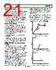
19 / 52 page  Data Sheet SSM4567 Rev. 0| Page 19 of 52 Figure 38. Basic Timing Diagram of Placements in I2S Stream Figure 39. Standard I2S Data Placement Timing Diagram Figure 40. TDM Serial Interface Format STEREO (I2S/LEFT JUSTIFIED) OPERATING MODE Stereo modes use both edges of the FSYNC signal to determine placement of data. Stereo mode is enabled when SAI_MODE = 0 and I2S or left justified is determined by the SDATA_FMT bit setting. In standalone mode or when AUTO_SAI = 1, an I2S output interface can be configured by exchanging the connections to the DAC_PDM_CLK/BCLK and SNS_PDM_CLK/FSYNC pins. The I2S and left justified interface formats accept any number of BCLK cycles per FSYNC cycle. Sample rates from 8 kHz to 192 kHz are accepted. The six placement control registers, SAI_PLACEMENT_x, determine placement of input and output data. Odd numbered placement control registers determine the order on the left channel and even number on the right channel. In the timing diagrams, these placements are refered to as P1 to P6. There are four placements for the incoming DAC data and six placements for the outgoing sense data. RIGHT JUSTIFIED DATA When the audio data in either a TDM or I2S slot placement is right justified, the Px_DAC bits can be used to properly read the data. Each Px_DAC bit has a setting where it reads in eight bits of data. The data is then not used and fulfills the read requirement for that slot so that the subsequent bits are read as the data of the next slot. This continues until a slot is reached that is set to read audio data. For example, for a stereo I2S, 24-bit audio data-word that is right justified with 32 BCLKS for the left channel, set P1_DAC to b10 so that it picks up the first eight bits of zero data. Then, set P2_DAC to b00 so that it picks up the 24-bit audio data. Fo another example, for a stereo I2S 16-bit audio data word that is right justified with 32 BCLKS for the left channel, set P1_DAC to b10 so that it picks up the first eight bits of zero data.Then, set P2_DAC to b10 so that it picks up the next blank 8 bits of data, and set P3_DAC to b01 so it then picks up the 16 bits of audio data. TDM OPERATING MODE TDM operating mode allows multiple chips to use a single serial interface bus. The FSYNC signal on the SNS_PDM_CLK/FSYNC pin operates at the desired sample rate. The rising edge of the FSYNC signal indicates the start of a new frame. For proper operation, this signal must be one BCLK cycle wide, transitioning on a falling BCLK signal edge. The MSB of data is present on the SNS_PDM_DAT/SNS_SDATAO pin one BCLK cycle later. The SNS_PDM_DAT/ SNS_SDATAO signal must be latched on a rising edge of the BCLK signal (see Figure 40). P1 8 BITS/16 BITS/24 BITS BCLK FSYNC DAC_SDATAI P3 P2 P4 VOLTAGE 16 BCLKs 16 BCLKs BATTERY CURRENT DAC INPUT 8 BCLKs BCLK FSYNC DAC_SDATAI DAC_SDATAO DAC DATA 1 ISENSE 1 VSENSE 1 BCLK FSYNC DAC_SDATAI DAC_SDATAO 24 16 16 32 BCLKS DAC DATA 2 ISENSE 2 |
|
Link URL |
| War ALLDATASHEET hilfreich? [ DONATE ] |
Über Alldatasheet | Werbung | Kontakt | Privatsphäre und Datenschutz | Link zum Datenblatt | Linktausch | Hersteller All Rights Reserved©Alldatasheet.com |
| Russian : Alldatasheetru.com | Korean : Alldatasheet.co.kr | Spanish : Alldatasheet.es | French : Alldatasheet.fr | Italian : Alldatasheetit.com Portuguese : Alldatasheetpt.com | Polish : Alldatasheet.pl | Vietnamese : Alldatasheet.vn Indian : Alldatasheet.in | Mexican : Alldatasheet.com.mx | British : Alldatasheet.co.uk | New Zealand : Alldatasheet.co.nz |
|
Family Site : ic2ic.com |
icmetro.com |
 German ▼
 English
 Chinese
 German
 Japanese
 Russian
 Korean
 Spanish
 French
 Italian
 Portuguese
 Polish
 Vietnamese
 Indian
 Mexican
 British
 New Zealand