|
Datenblatt-Suchmaschine für elektronische Bauteile |
|
|
Datenblatt-Suchmaschine für elektronische Bauteile |
|
MCP3912 Datenblatt(PDF) 54 Page - Microchip Technology |
|
|
|||||||||||||||||||||||||||||
MCP3912 Datenblatt(HTML) 54 Page - Microchip Technology |
|
|
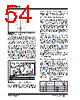
54 / 82 page  MCP3912 DS20005348A-page 54 2014 Microchip Technology Inc. FIGURE 7-4: Separation of Analog and Digital Circuits on Layout. Figure 7-5 shows a more detailed example with a direct connection to a high-voltage line (e.g., a two-wire 120V or 220V system). A current-sensing shunt is used for current measurement on the high side/line side that also supplies the ground for the system. This is necessary as the shunt is directly connected to the channel input pins of the MCP3912. To reduce sensitivity to external influences such as EMI, these two wires should form a twisted pair, as noted in Figure 7-5. The power supply and MCU are separated on the right side of the PCB, surrounded by the digital ground plane. The MCP3912 is kept on the left side, surrounded by the analog ground plane. There are two separate power supplies going to the digital section of the system and the analog section, including the MCP3912. With this placement, there are two separate current supply paths and current return paths, IA and ID. FIGURE 7-5: Connection Diagram. The ferrite bead between the digital and analog ground planes helps keep high-frequency noise from entering the device. This ferrite bead is recommended to be low resistance; most often it is a THT component. Ferrite beads are typically placed on the shunt inputs and into the power supply circuit for additional protection. 7.3 SPI Interface Digital Crosstalk The MCP3912 incorporates a high-speed 20 MHz SPI digital interface. This interface can induce a crosstalk, especially with the outer channels (CH0, for example), if it is running at its full speed without any precautions. The crosstalk is caused by the switching noise created by the digital SPI signals (also called ground bouncing). This crosstalk would negatively impact the SNR in this case. The noise is attenuated if a proper separation between the analog and digital power supplies is put in place (see Section 7.2 “Power Supply Design and Bypassing” ). In order to further remove the influence of the SPI communication on measurement accuracy, it is recommended to add series resistors on the SPI lines to reduce the current spikes caused by the digital switching noise (see Figure 7-5 where these resistors have been implemented). The resistors also help to keep the level of electromagnetic emissions low. The measurement graphs provided in this MCP3912 data sheet have been performed with 100 series resistors connected on each SPI I/O pin. Measurement accuracy disturbances have not been observed even at the full speed of 20 MHz interfacing. The crosstalk performance is dependent on the package choice due to the difference in the pin arrangement (dual in-line or quad), and is improved in the QFN-28 package. 7.4 Sampling Speed and Bandwidth If ADC power consumption is not a concern in the design, the boost settings can be increased for best performance so that the OSR is always kept at the maximum settings to improve the SINAD performance (see Table 7-1). If the MCU cannot generate a clock fast enough, it is possible to tap the OSC1/OSC2 pins of the MCP3912 crystal oscillator directly to the crystal of the microcontroller. When the sampling frequency is enlarged, the phase resolution is improved, and with the OSR increased, the phase compensation range can be kept in the same range as the default settings. MCU Power Supply Circuitry LINE NEUTRAL SHUNT Twisted Pair IA ID ID IA “Star” Point VA VD Analog Ground Plane Digital Ground Plane MCP3912 TABLE 7-1: SAMPLING SPEED VS. MCLK AND OSR, ADC PRESCALE 1:1 MCLK (MHz) Boost<1:0> OSR Sampling Speed (ksps) 16 11 1024 3.91 14 11 1024 3.42 12 11 1024 2.93 |
|
Link URL |
| War ALLDATASHEET hilfreich? [ DONATE ] |
Über Alldatasheet | Werbung | Kontakt | Privatsphäre und Datenschutz | Link zum Datenblatt | Linktausch | Hersteller All Rights Reserved©Alldatasheet.com |
| Russian : Alldatasheetru.com | Korean : Alldatasheet.co.kr | Spanish : Alldatasheet.es | French : Alldatasheet.fr | Italian : Alldatasheetit.com Portuguese : Alldatasheetpt.com | Polish : Alldatasheet.pl | Vietnamese : Alldatasheet.vn Indian : Alldatasheet.in | Mexican : Alldatasheet.com.mx | British : Alldatasheet.co.uk | New Zealand : Alldatasheet.co.nz |
|
Family Site : ic2ic.com |
icmetro.com |
 German ▼
 English
 Chinese
 German
 Japanese
 Russian
 Korean
 Spanish
 French
 Italian
 Portuguese
 Polish
 Vietnamese
 Indian
 Mexican
 British
 New Zealand